VISUAL INSPECTION OF INJECTIONS
If you find any inaccurate information, please let us know by providing your feedback here


Tóm tắt nội dung
- SCOPE
- BACKGROUND
- TYPICAL INSPECTION PROCESS FLOW
- INSPECTION LIFE CYCLE
- INTERPRETATION OF INSPECTION RESULTS
- Defect Classification
- Unique Product and Container Considerations
- DIFFICULT TO INSPECT PRODUCTS (DOSAGE FORMS, CONTAINERS, AND DELIVERY SYSTEMS)
- LYOPHILIZED PRODUCTS
- POWDER PRODUCTS
- EMULSION AND SUSPENSION PRODUCTS
- CELL AND GENE THERAPY PRODUCTS
- AMBER CONTAINERS
- PLASTIC CONTAINERS
- LARGE-VOLUME CONTAINERS
- COMBINATION PRODUCTS
- Alternate Inspection Strategies for Supplemental Testing
- INSPECTION METHODS AND TECHNOLOGIES
- QUALIFICATION AND VALIDATION OF INSPECTION PROCESSES
- PRODUCTS IN DISTRIBUTION
- CONCLUSIONS AND RECOMMENDATIONS
- REFERENCES
This article is compiled based on the United States Pharmacopeia (USP) – 2025 Edition
Issued and maintained by the United States Pharmacopeial Convention (USP)
1 SCOPE
1.1 Introduction
This chapter provides guidance on the inspection of injections for visible particles. The terms "particle," "particulates," and "particulate matter" are equivalent and do not have different meanings when used in this chapter. Particulate matter is defined in Particulate Matter in Injections (788) as "extraneous mobile undissolved particles, other than gas bubbles, unintentionally present in the solutions." Visual inspection is a probabilistic process, and the specific detection probability observed for a given product for visible particles will vary with differences in dosage form, particle characteristics (such as size, shape, color, and density), and container design. Some products and packages limit the ability to inspect for particles when compared to clear solutions in transparent containers. Additional guidance when inspecting these difficult-to-inspect products (DIP) are provided later within this chapter.
The requirement for injections to be "true solutions" appeared in USP IX in 1915, and the first appearance of "solution clarity" for parenteral products occurred in 1936 in NF IV. Since then, there have been numerous modifications to the compendia in this regard. A comprehensive history of compendial inspection standards is available in the Pharmacopeial Forum (1).
The practices discussed in this chapter are also applicable to the detection of other visible defects that are not the subject of Visible Particulates in Injections (790), but are critical to a qualified, comprehensive inspection process. These include, but are not limited to, container-closure integrity defects such as cracks, misplaced closures, or incomplete seals, any of which may compromise the sterility of the product. Additional container system defects (2-3), as well as other product characteristics such as fill level, discoloration, or clarity, may also be detected during visual inspection, and nonconforming units should be rejected using the methods described in this chapter. Inspection for these container-closure quality attributes often occurs at the same time as the inspection for particles using a specifically designed and qualified inspection sequence.
The reference method described in this chapter and in (790) is a manual inspection of a single container for particulate matter. However, multiple-container manual inspection, semi-automated, and automated inspection methods are also discussed and permitted by the Pharmacopeia. These alternate inspection methods must be qualified to demonstrate equivalent or better defect detection when compared to the reference manual inspection described in (790)
Change to read:
1.2 Related Chapters
Injections and Implanted Drug Products (1) provides an overview of injectable dosage forms and the quality tests associated with them. Another chapter, (790), has been added to the USP-NF to provide a clear definition of routine inspection procedures for injectable products; the goal is to comply with the expectation that products be essentially free of visible particulate matter. Additionally, information on the detection of subvisible particulates and particulates in specific dosage forms is provided in Ophthalmic Products-Quality Tests (771), Subvisible Particulate Matter in Therapeutic Protein Injections (787), (788), and Subvisible Particulate Matter in Intraocular Solutions (789) Measurement of Subvisible Particulate Matter in Therapeutic Protein Injections (1787), and Methods for the Determination of Subvisible Particulate Matter (1788) provide additional supporting information on measurement methods for subvisible particles.
1.3 Defect Prevention
Although this chapter focuses on the detection and removal of product units that show evidence of visible particles, the need for preventing such contamination should not be overlooked. No inspection process, manual or automated, can guarantee complete removal of all visible particulate matter or other visible defects; thus, prevention of such defects is an important consideration. Good process and product design, along with environmental control, are necessary to ensure the reliable production of products with a low particle burden. To ensure the control of defects throughout the process, manufacturers should consider an inspection life-cycle approach (4). This approach begins with developing quality attributes based on incoming component specifications, followed by component-level acceptance testing. It extends to component preparation and product-filling procedures, followed by 100% in-process inspection of filled product, and concluding with final acceptance sampling and testing of the finished product. The life-cycle approach must encompass purchased, ready-to-use (RTU) components such as primary containers or closures, where there is no opportunity for further particle removal before use. Single-use systems (SUS) and consumable cleanroom materials such as wipes, should also be considered as potential sources of particulates. Stability and retention sample inspection, customer complaint evaluation, and in-house investigative procedures support this integrated approach. The inspection life cycle is composed of and supported by sub-cycles involving defect detection method development, qualification of methods and personnel, maintenance, and personnel training. Categorization and identification of product-contact particles found during inspection are useful to support source identification. Forensic analytical methods and the use of libraries containing visual standards (e.g., photographs and/or drawings) and characterized defect samples further support these objectives. The final element of the life cycle is a feedback loop of trending and data review from each of these process areas, resulting in a quality system that supports continuous process improvement.
2 BACKGROUND
2.1 Inspection Process Capability
Visual inspection of injections is necessary to ensure articles for administration consistently exhibit a high-quality level and minimize the introduction of unintended particles to patients during the delivery of injectable medications. Such inspection also offers the opportunity to reject containers whose integrity has been compromised, such as those with cracks or incomplete seals, which pose a risk to the sterility of the product. The desire to detect these defects, despite their very low frequency and the randomness of their occurrence, has resulted in the longstanding expectation that each finished unit will be inspected (100% inspection). Although having zero defects is the goal and this should drive continuous process improvement, zero defects is not a feasible specification for visible particles given current packaging components, processing capability, and the probabilistic nature of the inspection process.
The visible particulate detection process is probabilistic: the likelihood of detection is a cumulative function of visible attributes such as particle quantity, size, shape, color, density, and reflectivity as well as optical characteristics of the surrounding product and package. Understanding human performance is therefore critical to establishing visual inspection criteria. Analysis of inspection results pooled from several studies (5-7) conducted with standards prepared with single spherical particles shows that the probability of detection (PoD) for a seeded sample with a single 50-µm particle in a clear solution contained in a clear 10-mL vial utilizing diffuse illumination between 2000 and 3000 lux is only slightly greater than 0%. The detection probability increases to approximately 40%-60% for a seeded standard with a 100-µm particle, and the threshold for routine, reliable detection (≥70% PoD) of individual visible particles is often near 150 µm in diameter. Particles 200 µm and larger are often necessary to achieve greater than 95% PoD (5). The PoD for fibers is often less than that discussed for similarly sized spherical particles above, with reliable detection often commencing at or above 500 µm (Z). Thus, in a qualified visual inspection system, the vast majority of nonfibrous particles that might go undetected and be introduced into the pharmaceutical supply chain will be smaller than 200 µm. Some injectable products are more difficult to inspect due to the nature of the primary container (8) (e.g., increasing size, color, and opacity), as well as dosage form characteristics (e.g., fill level; solution color, clarity, or opalescence; and suspensions, lyophilized powders, emulsions, and implants). Particle characteristics beyond size (e.g., color, shape, and density) will also affect the PoD that can be achieved for a specific product and container system (Z).
2.2 Patient Risk
A complete review of the medical literature is beyond the scope of this chapter, but the effect of particles on the patient must be considered. Several reviews on this subject are available (9-15). The clinical implications of particulate matter in injections are determined by many factors, including the size and number of particles, the composition of the material, the potential for microbiological contamination, the route of administration, the intended patient population, and the clinical condition of the patient. For example, an otherwise healthy individual receiving a subcutaneous or intramuscular injection containing sterile, inert particulates would likely experience no adverse effects, or at worst would develop a small granuloma. On the other hand, a critically ill premature infant receiving a particle-laden infusion directly through an umbilical catheter might suffer considerable pathophysiologic injury (16-17).
Numerous animal studies have been conducted to determine the fate of intravenous particles with different sizes and compositions (18-21). Most studies have focused on subvisible particles with a diameter <50 µm. In these studies, a massive infusion of particles has been accompanied by histologic evidence of injury to pulmonary capillary endothelial cells (22), microscopic thrombi in the pulmonary capillaries (23), pulmonary microscopic granulomata (24), and hepatic inflammatory effects (25). Although useful for understanding the pathophysiologic response to particulate matter, the large number of particles used in these studies (e.g., 10º particles/kg per injection) provides little insight into the risk to humans posed by small numbers of visible particles.
Garvin and Gunner were among the first to report a concern about the effects of particles in human patients (26-27). For obvious ethical reasons, there is a lack of controlled clinical studies on the effects of particles purposely infused into human patients. Some anecdotal information about human patient safety may be obtained by examining case reports of intravenous drug abusers (28-30). In these cases, solid oral dosages are often ground up and injected as a slurry; pulmonary foreign-body emboli and granulomas were observed in these patients (31). Unfortunately, the clinical risks to human patients posed by small numbers of particles are difficult to infer from these observations due to the extreme number of insoluble particles and the uncontrolled conditions in which they were administered.
Arterial embolization using materials such as polyvinyl alcohol (PVA), collagen-coated Acrylic microspheres, and gelatin spheres also provides some insight into the potential human pathophysiologic implications of non-target embolization of extraneous-particle intravenous infusions. In these cases, massive particle loads moving from the arterial injection site into the venous circulation were also reported (32-36). In addition, case reports have documented injury associated with the infusion of significant quantities of precipitated admixtures or therapeutic use of particles for embolization (16-17.37). Finally, recent studies evaluating the utility of in-line filtration (0.2- and 1.2-um-rated filters) of intravenous fluids administered in a pediatric intensive care unit setting suggest that reducing the particulate burden associated with high volume infusions and multiple infused medications through bedside filtration may provide a reduction in morbidity in select patient populations (38).
Ultimately, the safety considerations related to particulate matter in injections must be assessed for each drug product, intended patient population, and method of administration. No single set of inspection criteria can adequately anticipate all potential risks to the patient. Despite the administration of an estimated 15 billion doses of injectable medicines each year (39), no reports of adverse events associated with the injection of individual visible particles have been found. The methods outlined in (790), should serve as essential requirements when assessing the adequacy of the visual inspection procedure, but alternative acceptance criteria (e.g., the use of tightened sampling plans) should be implemented when the patient population and intended use of the product warrant these additional measures.
3 TYPICAL INSPECTION PROCESS FLOW
3.1 100% Inspection
Chapter (790), establishes the expectation that each finished unit of injectable product will be inspected as part of the routine manufacturing process. This inspection should take place at a point when and where defects are most easily detected, for example, prior to labeling or insertion into a device or combination product. Each unit should be examined with the unaided eye under conditions appropriate for the container system (manual inspection) or by using a conveyor to transport and present the containers to a human inspector (semi- automated inspection), or by means of light obscuration or electronic image analysis (automated inspection). Manual and semi-automated inspection should be performed only by trained, qualified inspectors. Inspection may be conducted by means of a device that holds more than a single unit at one time for examination. This inspection may be performed at-line or in-line with filling or packaging or in a separate, off-line inspection. The intent of this inspection is the detection and removal of any observed defective unit. When in doubt, units should be removed. Figure 1 shows a simplified process flow where solid boxes indicate required process operations, and those with dotted lines (supplemental testing) may be required for DIPs as discussed in 5.2 Unique Product and Container Considerations. Alternative strategies, such as reinspection or two-stage inspection, may be required and are discussed in 3.3 Remediation and Alternative Practices.
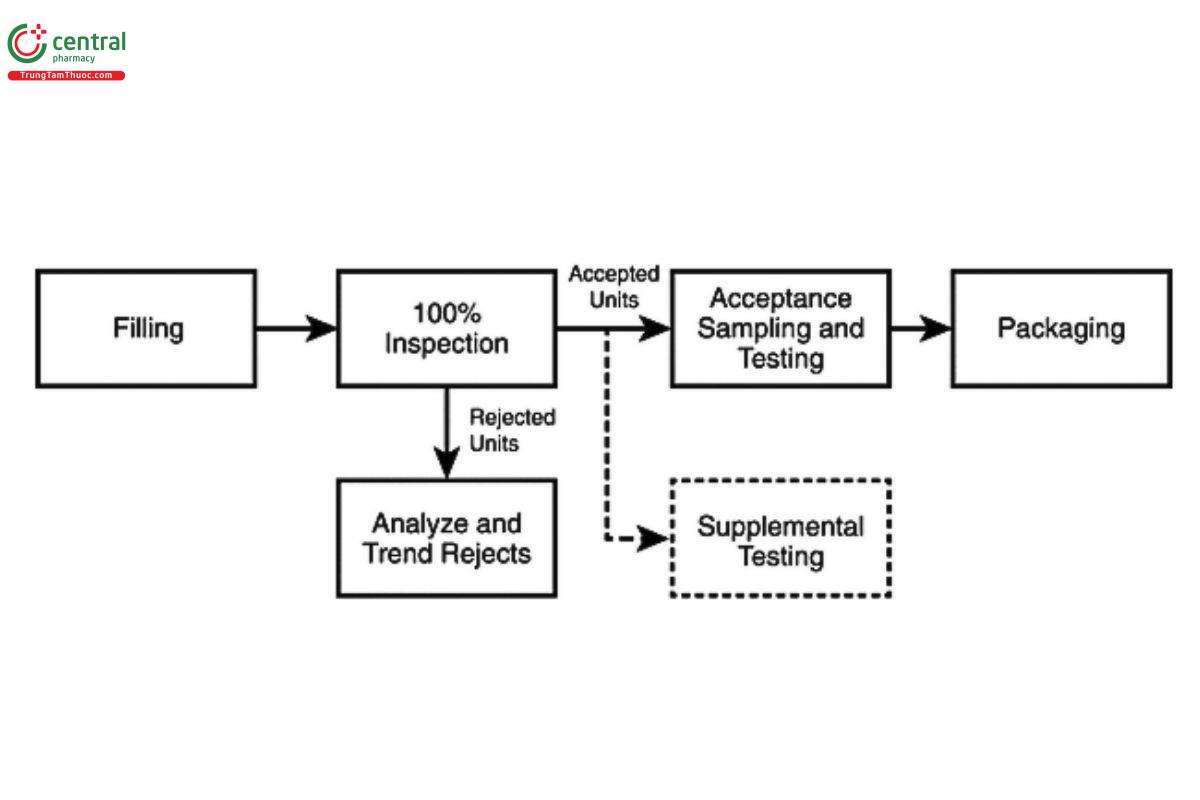
[NOTE-100% inspection refers to the complete non-destructive inspection of the container-closure system and its contents. Inspection may be accomplished in a single operation with specifically designed sequences for detecting visible particulate and/or container system defects or in multiple steps using a combination of technologies. See additional discussion in 3.3 Remediation and Alternative Practices and 6. Inspection Methods and Technologies.]
[NOTE-Supplemental destructive testing is required when the nature of the product or container limits visual inspection of the contents (e.g., with a lyophilized cake or powder, or with an amber glass or opaque container). See additional discussion in 5.2 Unique Product and Container Considerations. Representative samples should be taken throughout the batch for supplemental testing from any point in the process after 100% inspection.]
During 100% inspection, limits on typical rejection rates should be established to identify atypical lots (40). These limits may be established for categories of defects (e.g., critical, major, and minor) or for specific types of defects (e.g., particles). A review of historical performance is useful in establishing these limits, and the review may include grouping products similar in appearance and manufacture. Periodic reassessment of these limits is recommended to account for expected process improvements and/or normal fluctuations in the process baseline (41). If a limit is exceeded, it should trigger an investigation. The investigation may include an additional inspection, or it may determine whether additional inspection is necessary.
3.2 Acceptance Sampling and Testing
After 100% inspection, a statistically valid sample is taken from the units accepted by the inspection process. These sampled units should be manually inspected under controlled conditions by trained inspectors. Chapter (790), provides reference inspection conditions for this purpose. The sample may be a random or a representative sample (e.g., at fixed time intervals or a fixed number per tray). Defects may not be distributed equally over the lot, and therefore a sampling process that represents the whole lot is required. Typical sampling plans used for this purpose can be found in ANSI/ASQ Z1.4 (42). Equivalent plans may also be found in ISO 2859 (43) or JIS Z9015 (44). These plans were historically developed for larger lot sizes and thus oversampled smaller batches (45). Alternative sampling plans may be justified for smaller batch sizes resulting in a smaller sample size. For batch release, the sampling plans listed as Normal II are typically used. Tightened sampling plans may be appropriate when an atypical result is observed, or reinspection is performed. All sampling plans specify a sample size for a range of batch sizes and require selection of an acceptable quality limit (AQL) to establish the sensitivity of the plan. The AQL is the defect rate at which 95% of the lots examined will be accepted and is a measure of falsely rejecting good batches. Critical defects (those that pose the greatest risk to the patient) should be assigned an AQL with a very low value. Often, the accept number (the number of defective units allowed in the sample) for a critical defect is zero. Major and minor defects, which pose less risk to the patient, will have increasing (less stringent) AQL values and accept numbers greater than zero. Further definition and discussion on defect categories are found in 5.1 Defect Classification. Table 1 shows the range of AQL values typically used for visual inspection processes (46).
Table 1. Typical AQL Values for Visual Inspection Processes.
| Defect Category | AQL Range (%) |
| Critical | 0.010 – 0.10 |
| Major | 0.10 – 0.65 |
| Minor | 1.0 – 4.0 |
| [NOTE-When selecting a sampling plan for AQL testing after 100% inspection using ANSI/ASQ Z1.4, ISO 2859, or JIS Z9015, choose the sample size to satisfy the AQL value for the most critical category (e.g., critical) of defects being evaluated. Then use the accept numbers for this sample size for the AQL values chosen for the other defect categories (e.g., major and minor). This assures that the sample size will produce a statistically valid result for all defect categories examined. The defect categories shown here represent a common basic approach to grouping defects by risk; however, additional categories may be added to these for more detailed analysis.] | |
While the standards referenced in the paragraph above are indexed by AQL, it is important to also know the unacceptable quality limit (UQL) for the sampling plan(s) used. These can be found in the operational characteristic (OC) curve data supplied for each plan found in these standards or calculated independently using qualified software. The UQL is the defect rate at which 90% of the lots examined will be rejected and is a better measure of the customer or patient risk. The protection afforded by any sampling plan is represented by its OC curve. This is a plot of the probability of lot acceptance versus the defect rate in the lot. The AQL and UQL are two points on this curve. Sampled units should be manually inspected under controlled conditions by trained inspectors. Inspection conditions should be aligned with the 100% inspection process.
Manual acceptance sampling should be performed after any type of 100% inspection process, including manual, semi-automated, and automated inspection processes. It provides a measure of the performance of the overall inspection process and the quality of a specific lot, compared with predefined acceptance criteria. Although automated systems are validated before use and are routinely challenged to ensure acceptable performance, the use of manual acceptance sampling inspection detects unexpected defects that were not included in the development and training of the automated system by the manual inspection process.
Acceptance criteria are comprised of the product specifications and acceptance/rejection criteria, such as the AQL and UQL values, with an associated sampling plan that is necessary for deciding to accept or reject a lot or batch (or any other convenient subgroups of manufactured units) as described in 21 CFR 210.3 (47). If the acceptance criteria of the sampling plan are not met, an investigation should be conducted. Depending on the nature of the failure, this investigation should include forensic classification/identification of the particle(s), and examinations of the manufacturing process, the raw materials, and the packaging materials, as well as the inspection process. If, after investigation, the inspection process is deemed capable of detecting the defect(s) in question, the batch may be reinspected. An alternative inspection process better suited to detection of a specific defect may also be chosen for reinspection.
After reinspection (performing a second 100% inspection of the batch), a new statistically valid sample of the accepted units is taken and compared against established acceptance criteria. It is a good practice to use a tightened sampling plan and acceptance criteria under these circumstances because of the atypical nature of this process step.
Typical sampling plans for supplemental testing can be found in the special sampling plans S-3 and S-4 in ANSI/ASQ Z1.4 (42). These higher sensitivity S-plans offer a practical compromise between sample size and statistical power. For batch sizes between 200 and 100,000 they suggest a sample size of 20 with an accept number of 0 (based on an AQL of 0.65%). Sample sizes larger than 20, as found in these sampling plans, may be appropriate for larger batch sizes or when additional sensitivity to support reduced AQL values or a more conservative defect classification is desired. Refer to Table 2.
Table 2. Typical 0.65% AQL sampling schemes for normal, single-pass inspection using S-3 and S-4 levels, dependent upon lot size.
| Lot Size | (Sampling Letter Code) Accept Number, Reject Number/Sample Size | |
| Inspection Level S-3 | Inspection Level S-4 | |
| 200–10,000 | (F) 0,1 / 20 | (G) 0,1 / 20 |
| 10,001–500,000 | (G) 0,1 / 20 | (J) 1,2 / 80 |
| >500,000 | (H) 1,2 / 80 | (K) 2,3 / 125 |
Alternative plans are acceptable, but care should be taken to examine the UQL of such plans to assess their sensitivity.
3.3 Remediation and Alternative Practices
3.3.1 REINSPECTION
As discussed in the preceding section, reinspection (repeating the 100% inspection followed by acceptance sampling inspection) may be appropriate if the initial 100% inspection is not successful in meeting in-process control levels or the initial acceptance sampling inspection criteria. This includes instances when the established 100% inspection failure rate(s) and/or the accept/reject number(s) associated with the chosen AQL values have been exceeded. Reinspection should only be conducted using a procedure that has been approved by the quality organization and addresses key parameters such as the inspection conditions (e.g., same as primary inspection or modified to enhance detection of a specific defect type), the number of times reinspection may be performed (this should be limited and justified), and the acceptance criteria (e.g., same as primary inspection or tightened). If reinspection is required often, consideration should be given to improving the sensitivity of the primary inspection process or of the manufacturing controls to prevent defects in the upstream process as determined by root cause analysis.
3.3.2 TWO-STAGE INSPECTION
In cases where an assignable cause, such as the formation of air bubbles or specific container or closure variation, results in a high false-rejection rate (rejection of acceptable units), the use of a second inspection step may be considered. Figure 2 shows a typical process flow for a two-stage inspection. Such an inspection strategy is more common with automated inspection systems, where there is less ability to tolerate normal variation in the product or container.
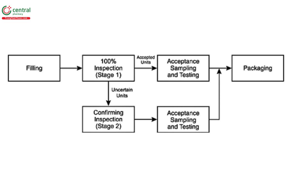
Under these circumstances, the inspection system is adjusted to ensure acceptance of good units. Those not accepted during the primary inspection are considered of uncertain disposition until inspected by another means (e.g., enhanced manual inspection) to provide confirmation of acceptance or rejection. Inspection conditions may be adjusted to provide greater sensitivity in this second inspection step (e.g., additional inspection time) to ensure a higher probability that true defective units will be rejected. The limitations of the first inspection and the reason for conducting a second stage of inspection should be clearly defined and documented. The second inspection of these units by the same method and conditions (e.g., automated inspection with the same parameters after an initial automated inspection) is generally not recommended because the same limitation in inspection method is present for both inspections unless enhanced manual or more sensitive automated inspection parameters are employed for the second stage inspection. However, it may be suitable when the root cause is specifically related to air bubbles in the solution, and a study has been performed to establish an appropriate holding time to allow the bubbles to dissipate before performing the second inspection. It is recommended that each inspection stream (those accepted by the first stage and those accepted by the second stage) be sampled separately and evaluated against the sampling plan acceptance criteria before they are confirmed as accepted and recombined into a single batch. If a two-stage inspection strategy is used, it must be validated as intended for use. Defective containers with less than a 100% PoD will have the PoD reduced further with each stage of inspection; thus, the PoD should be determined after inspection through both stages to ensure that acceptable sensitivity is maintained.
4 INSPECTION LIFE CYCLE
4.1 Extrinsic, Intrinsic, or Inherent Particles
Particles may originate from many sources. These are discussed here, as well as in other chapters in the USP (e.g., (1787)). Those that are foreign to the manufacturing process are exogenous or "extrinsic" in origin, these include hair, non-process-related fibers, starch, minerals, insect parts, and similar inorganic and organic materials. Extrinsic material is generally a one-time occurrence and should result in the rejection of the affected container in which it is seen; however, elevated levels in the lot may implicate a broader contribution from the same source. These particles may carry an increased risk of microbiological or extractable contamination because less is known about their path prior to deposition in the product container or their interaction with the product.
A second category of undesired particles is considered "intrinsic" or from within the process. The determination of whether the particulate is extrinsic or intrinsic to the process is based upon appropriate characterization of the particle's physicochemical properties. Process-related intrinsic particles may come from production equipment or primary packaging materials that were either added during processing or not removed during container or closure cleaning and preparation. These primary product-contact materials may include stainless steel, elastomers from seals and gaskets, container glass or plastic, fluid transport tubing, and silicone lubricant. Such particles still pose the risk of a foreign body, but they generally come from sterile or sanitized materials, and more is known about their interactions when in contact with the product. Any process-related intrinsic particles should have controls established based on the use of a life-cycle approach, as outlined in 1.3 Defect Prevention. Another group of particles considered intrinsic is interrelated with the stability of the product. These product-stability-indicating particles arise from container or closure interaction (glass delamination, component erosion, and elemental extraction), changes to the drug preparation (insoluble degradation products), recrystallization, or temperature sensitivity over time. Stability-indicating intrinsic particles should be identified and addressed as early in the product development process as possible.
A third category is that of an inherent particle type that varies with dosage form and includes solutions, suspensions, emulsions, and other drug delivery systems that are designed as particle assemblies (agglomerates, aggregates). Such dosage-form-related particulates should be studied in the development phase and in samples placed on stability to determine the normal characteristics and time-based changes that can occur. Measurement of particle size distribution or characterization by image analysis in the subvisible (for particle sizes 22 µm) and visible ranges (≥100 µm) may be required to fully characterize inherent dosage-form-related particles. In biologics, protein particles are generally considered inherent and may be accepted when their presence is measured, characterized, and determined to be part of the clinical profile. Aggregation or agglomeration of proteins associated with a change in preparation constituents or other causative agents like excessive siliconization should be minimized. The manufacturer may allow inherent particles if the product appearance specification allows their presence or if the product is an emulsion, suspension, or implant..
An evaluation of the potential impact of particles identified from any of these sources may be enhanced by incorporating a clinical risk assessment (15). This assessment may include factors such as the intended patient population, route of administration, source and type of particles, and implications for product sterility. For intrinsic or inherent particulate matter sources, a risk assessment may be useful in developing product-specific control strategies. Given the probabilistic nature of particle detection, it is important to assess the possible implications of particles identified through the product life cycle to better ensure the product's safe use.
4.2 Prevention of Particulates
The manufacturing process is designed to keep the final container and its contents clean within the control parameters established for process-related particulates. Once the container is filled, the stability of the product needs to be maintained throughout its shelf life. Changes that occur as the product ages during its normal shelf life must be characterized. Avoidance of intrinsic particle sources that may affect final product stability depends on careful consideration of the entire product and packaging system. If these intrinsically sourced changes occur, and they affect stability, particles ranging from subvisible to visible may develop. Typically, these particles result from change mechanisms that slowly affect the on-shelf product.
4.2.1 ROBUST DESIGN DURING DEVELOPMENT
To anticipate potential sources of instability that yield intrinsic particles, the product design should be evaluated from many perspectives, beginning with a literature review of similar preparations and packages. Points to consider include the reported sensitivities of the active ingredient, the dosage form type, and the final container-closure system needed for delivery. Knowledge of how glass containers are fabricated, controlled, sterilized, and tested is important as this may affect the tendency to form glass lamellae as discussed in Evaluation of the Inner Surface Durability of Glass Containers (1660), and by the FDA (48).
Obtaining further information on possible extracts and leachates, metals, or solubility limits is important as these factors may promote formation of solid material in the aging solution. Several additional factors for successful product design include the product concentration, solution pH, associated buffers, critical micelle concentration, oligomerization content/potential, package effects (large surface area, product volume, headspace, light/oxygen transmission), and compatibility of the specific preparation with the package. Furthermore, shock/vibration sensitivity at the air/liquid interface can be a significant contributor to particle formation that requires investigation during product development. Some key dosage form design factors include the formula components chosen and their purity, the solubilities of the active ingredient(s) and excipients, and consideration of potential salt forms. Finally, to maximize product stability, consider the final product preparation for delivery, product dilutions, and shelf stability of the commercial product or its therapeutic preparations.
To examine the appropriateness of the product design for maintaining product stability, there are two levels of evaluation. Both levels examine retained containers for visible changes using methods described in this chapter, but neither level dwells on low percentage defects.
For the first level of stability study, visual inspection and testing of trial containers will show general compatibility of the chosen components over time with regard to clarity, color, and both subvisible and visible particle formation. Careful product assembly in clean containers, with consideration of the container type, headspace, and sealing, will yield a beneficial first-pass trial of stability over several months' time. The nature of particles detected, and the investigation of type and frequency, is essential to differentiate additive types from instability or package interaction. Pursuit of extrinsic particles at this stage of development is generally not significant, as the particles do not reflect on the suitability of the specific preparation or expected manufacturing process under development but rather the way these study samples were prepared.
The second, more refined level of stability study involves conducting visual inspections of the injection in defined, International Council for Harmonisation (ICH)-relevant trials (49). This may include periodic inspection of the same containers over time if the product does not require reconstitution or is not affected by frequent temperature changes. Detection of minor or subtle differences in these containers is not the goal at this stage of development. Catastrophic change and the occurrence of intrinsic product-related visible particles should be the focus. Typically, a set of containers is carefully prepared to exclude extrinsic particles and is then inspected to cull out any units with visible defects. Next, a numbered set of containers appropriate for the batch size is placed on stability and visually inspected periodically for changes due to degradation or any sign of instability. It is important to be able to analyze the particulate matter or condition (change in color, turbidity, opalescence) to identify the cause of events due to instability. A typical sample size is 80-100 units. This quantity should be sufficient to assess package and preparation interaction. Additional sets of containers stored at selected extremes of ICH temperatures can be followed to aid discovery of solubility-edge phenomena. When unwanted changes are detected-such as particle formation, solution color change, solution haze, and package changes-the process of isolation, characterization, and identification can commence. Identification of the material comprising these changes aids in the determination of the cause of formation as well as development of improvements for future use.
4.2.2 COMMON SOURCES OF PARTICULATES
Process-related intrinsic particles originating from product-contact materials tend to be stable and unchanging (e.g., glass, elastomers, or metal). In contrast, there may also be particles resulting from product-stability-related change mechanisms within the final product. It is very important to understand that these changes only need be slight in certain cases, far below the detection limit of most release or stability assays, to result in visible changes to the product. The threshold levels for the formation of visible change for certain substances may be as low as 10-100 ppm (0.001%-0.01%) based on the ability to detect a single 100-µm particle or many sub-10-µm particles creating a hazy or cloudy appearance. However, if all this insoluble material were contained in a single particle, it likely would not cause rejection of the container.
4.2.3 DOSAGE FORM COMPONENTS
The active ingredient may also contribute to the presence of stability-indicating intrinsic particles. For example, significant haze and particles have been observed in aqueous dosage forms due to extraction of plasticizers from filtration media during bulk drug production (6). Metal content in the active ingredient has contributed to organometallic salt formation and has also been observed as precipitated inorganic salts, blooming long after product release. The active ingredient and related degradation products may also be relatively insoluble and may grow to form visible particles. Isolated particulate material must be analyzed to determine its chemical nature and possible source.
Monomers or single molecules may join through chemical processes to form dimers, trimers, and oligomers (a limited assemblage of monomers, short of polymerization). Such changes are not unexpected (50). In high-concentration and/or saturated preparations, and especially for micellar drug associations, the solubility of related forms is significant when the aging preparations contain progressively higher concentrations of these substances. Larger molecules may have a greater effect on solution integrity due to their inherent insolubility, especially if the active drug is in a micellar preparation.
Polymorphs are unique crystalline forms of identical chemical entities. Although uncommon in solutions that have been mixed homogeneously and filtered, small seed crystals of a relatively stable polymorph may form over time, especially at nucleation sites such as container-surface defects. More common than formation of polymorphs is the formation of a modified crystal lattice containing an integral liquid, typically water or a solvent. The lattice may form slowly, promoted by evaporation, nucleation, and temperature extremes (51-52).
4.2.4 PACKAGING COMPONENTS
"Extractables" and "leachables" are terms commonly used to describe the potential for primary packaging materials to contribute unwanted agents to the product. Extractables represent all the materials that could be contributed, and leachables represent the practical contribution upon contact between packaging components and drug preparation as discussed in Assessment of Extractables Associated with Pharmaceutical Packaging/Delivery Systems (1663), and Assessment of Drug Product Leachables Associated with Pharmaceutical Packaging/Delivery Systems (1664), as well as in other references (53). These substances can also contribute to the formation of subvisible and visible particles. All product contact materials should be evaluated for extractables and leachables or product reactivity.
Product preparation attack of the container is a dramatic change and most often occurs in glass container systems. Glass containers undergo corrosion that is 25 times greater at pH 8 than at pH 4 (54, (1660)). A preparation with a pH above 7, especially with high-ionic strength solutions, promotes attack of the inner glass surface, resulting in glass delamination and/or siliceous particle generation.
Silicone oil is added to stoppers and prefilled syringe systems to enhance lubricity for stopper or plunger insertion and its movement within the syringe barrel. Silicone may also come from tubing used for fluid transfer and a variety of polymeric fittings and seals that are used in the processing equipment. All these components must be compatible with the preparation to minimize leachates. Although silicones are processed to be sterile and are widely used, their use must still be strictly controlled, in other words, minimized. Silicone can cause container sidewall droplets and a variety of visible semisolid forms. No more than the minimum quantity should be used during processing to achieve acceptable machineability. Silicone and other hydrophobic substances have the capacity to coalesce and agglomerate with proteinaceous drug substances (55) or other particles, eventually reaching a visible size over time.
Residual tungsten from the manufacture of syringes has been known to increase protein aggregation (56).
4.3 Recommendations for Specific Components and Processes
4.3.1 GLASS CONTAINERS
Each step of the glass-container washing and rinsing process performed internally or by an external supplier, should be evaluated for particle-reduction capability. Incoming glassware may have significant particle load. The washer validation studies should demonstrate a reduction in naturally occurring particles (particle burden) or should use seeded containers to demonstrate such reduction capability. The use of statistical sampling plans with light obscuration (LO) for subvisible particle levels and membrane-microscope particle-counting method for the enumeration of visible particles can provide a means to demonstrate reduction of both subvisible and visible particles during washing cycle development and validation. The membrane filtration microscopic method is superior to the LO method for capturing and characterizing larger foreign particles in the visible range (>100 µm) during validation or monitoring activities. During process development, validation, and routine use, container-washing procedures should include periodic visual operational checks. This routine verification ensures that effective draining of all containers is occurring during all washing and rinsing steps. Review the wash-water recirculating filter maintenance procedures to ensure that particle overloading or breakthrough is being prevented.
Glass breakage that occurs during the component washing process could affect surrounding containers, and the washing cycle should be evaluated for possible glass particle generation and distribution. Written procedures describing container-clearance following glass breakage in the washer, in the depyrogenation tunnel, or on the filling line should specify the number of containers to be removed from the affected portion of the line. Removing units around the immediate area where the breakage occurred aids in minimizing particle transfer to the downstream process.
Processes that use racks or trays for transporting and holding samples, as are typically used in batch ovens, should be monitored for metal particle generation. The racks or trays should have a formal maintenance program associated with their routine use. Trays should be inspected for wear and scoring, which can be sources of particulates. Periodic cleaning, polishing, and/or resurfacing may be warranted to control particles effectively. Tunnels used for depyrogenation should also have a routine maintenance program for periodic cleaning, inspection, and replacement of parts that may wear and generate particles. Glass-to-glass and glass-to-metal contact should be minimized where possible to reduce weakening of the glass surface resulting in increased risk of subsequent fracture. The use of polymeric facing on guides can help to reduce such damage; however, coatings on metal surfaces must be monitored for degradation or particle generation by frictional wearing over time.
4.3.2 ELASTOMERIC CLOSURES
Each step of the elastomeric-component washing and rinsing process should be evaluated for particle-reduction opportunities. Utilize statistically valid sampling plans to collect meaningful test units. The use of LO (for subvisible particles) or other automated particle counting or membrane-microscopic particle-counting methods may be used to demonstrate reduction of both subvisible and visible particles during washing validation. As stated above for glass containers, the membrane filtration microscopic method is superior to LO methods for capturing and characterizing larger foreign particles in the visible range (>100 µm) during validation or monitoring activities with elastomeric closures. During process development and validation and in routine use, container-washing procedures should include visual checks to ensure that stoppers are not routinely sticking together. Such sticking surfaces reduce cleaning efficacy and entrap particles or cause reduced sterilization and depyrogenation effectiveness. Periodic assessment of component cleanliness and supplier washing capabilities should be included as part of the supplier qualification program when using ready-to-sterilize (RTS) or RTU components.
Evaluate siliconization processes, whether in-house or by the supplier, to minimize excess silicone levels while maintaining machinability of the stoppers. LO or other automated particle-counting methods may be used to compare overall particle level reduction (subvisible background silicone oil droplets) during process development or validation. The level of residual silicone oil will affect the particulate quality of the final filled product, observed as dispersed droplets and particle-forming matrices.
4.3.3 EQUIPMENT PREPARATION
It is important to minimize redeposition of particles on product contact surfaces after cleaning. Cleaned and sterilized equipment should be protected by HEPA-filtered, unidirectional airflow until transferred to, and installed on, the filling line. For cleaned equipment that needs to be wrapped or bagged prior to sterilization, utilize low-shedding, noncellulosic (synthetic) wrapping materials. Cellulose fibers are one of the most common particles found in the injections-manufacturing environment, and injectable products and their source will be a prime concern (46).
Personnel are a concern for the introduction of extrinsic particle types such as facial hair and skin cells. The equipment preparation staff should be adequately gowned with hair covers, facial hair covers, and goggles to prevent contaminating cleaned process equipment. During validation and monitoring activities of clean- and/or steam-in-place (CIP-SIP) systems (vessels, filters, tubing, and other product contact equipment), foreign particle burden should be evaluated after cleaning. Membrane filtration/microscopic-particle-capture and -counting methods provide a useful tool to assess and document performance.
4.3.4 FILLING LINE
The transfer of open containers should be evaluated and reviewed to mitigate particle contamination. For example, for aseptically filled products, the transfer should be conducted in Grade A (ISO 5, Class 100), unidirectional airflow to minimize particle contamination. The air in critical zones should be monitored continuously during operation to confirm compliance. Routine checks to detect particles and potential particle-generation locations should be explained in the procedures. Effective, written container-clearance procedures to be used after glass breakage should specify the number of containers to remove from the affected portion of the line. Note that improper setup and adjustment of the filler can lead to "needle strikes," where the filling needles contact the container being filled. This can generate either stainless steel or glass particles.
Filling pump design and the pump's compatibility with the product are important considerations. Metal-on-metal piston pumps have the potential for generating metal particles. Pump maintenance is essential and includes a requirement to resurface the cylinders and pistons periodically. Peristaltic-action pumps must be monitored for generation of silicone tubing particles, especially with aggressive, near-saturated solutions or suspensions. Friction in the peristaltic roller area can break down the tubing, resulting in the generation of particles (spallation). Diaphragm pumps must have specific maintenance cycles to replace the pump lining.
Stopper bowl surfaces should have a formal maintenance program, and stopper handling or replenishment by operators should be specifically designed to minimize particle transfer to the stoppers. Proper operator positioning and avoidance of open containers is important in good aseptic-filling practices to avoid microbial contamination. These same principles help reduce particle transfer to the open containers and exposed elastomeric closures.
Careful selection of cleaning and gowning materials will help reduce contamination from extrinsic particles and fibers. These clean-room materials (typically polyester or Tyvek) should be selected for their superior non-shedding and low-particle properties.
4.4 Trending
Data obtained from the in-process 100% inspection followed by AQL inspection are used for batch release. Both 100% and AQL inspection data should also be analyzed for adverse trends on a periodic basis, typically at least annually. Data from the 100% inspection provides the best source of typical defect types and rates during normal production. High-volume products may generate enough data to allow quarterly analysis, whereas a longer period may be necessary to accumulate data for products that are produced infrequently. Data from component inspection, production 100% inspection, and the AQL inspections should be evaluated based upon sound statistical principles to determine whether the current action levels accurately reflect current process capability. Alert and/or action levels may be established and/or adjusted if the statistical analyses indicate that lower defect levels are being observed consistently. When establishing new action or alert levels, a preliminary target value may be used until enough production experience is obtained. Consideration should be given to planned improvements in the manufacturing and inspection processes. If significant improvements are planned, the reduction of the action/alert level should not be instituted until the impact of the improvement is measured over enough time to establish the validity of the new value.
5 INTERPRETATION OF INSPECTION RESULTS
5.1 Defect Classification
Defects are commonly grouped into classifications based on patient and compliance risk (2). The most common system uses three groups: critical, major, and minor. Critical defects are those that may cause serious adverse reactions or death of the patient if the product is used. This classification includes any nonconformity that compromises the integrity of the container and thereby risks microbiological contamination of the sterile product. It may also include anomalous extrinsic particle types such as insects or other filth or adulteration. Major defects carry the risk of temporary impairment or medically reversible reactions or involve a remote probability of a serious adverse reaction. Visible intrinsic particulate matter typically falls into the major defect category. This classification is also assigned to any defect that impairs or makes the product unusable. Minor defects do not impact product performance or compliance; they are often cosmetic in nature, affecting only product appearance or pharmaceutical elegance.
Upon 100% inspection, visible extrinsic and intrinsic particles should be reliably removed. Particle motion aids in detection, and stationary particles (due to neutral buoyancy or fill viscosity) are difficult to detect, exhibiting a significantly reduced PoD. The test method allows inherent particles to be accepted if the product appearance specification allows inherent particle types. PoD for all particles is dependent on the container characteristics (e.g., size, fill level, shape, and transparency), inspection conditions (lighting and duration), preparation characteristics (color and clarity), and particle characteristics (size, shape, color, and density). The PoD at 70% or greater is known as the "reject zone" described in Knapp's methodology (57-58), which is used worldwide as a common industry practice for rejecting particle defects. Test sets characterized by repeated inspections, as described in 7.4 Rejection Probability Determination, are used to "calibrate" the inspection method's PoD, inspector performance, or automated inspection systems, and to demonstrate the sensitivity to threshold particle size at the reject zone of >70% PoD. The limitation of the reject zone at 70% detection is that threshold particles at this size may routinely be missed or go undetected up to 30% of the time. These undetected units may contain some level of threshold-sized particles or subvisible particles at a lower PoD. Therefore, it is important to characterize and size any particles recovered from AQL testing, retention sample inspection, and product returned from distribution to understand how they could have gone undetected during the initial 100% in-process inspection.
5.2 Unique Product and Container Considerations
5.2.1 DIFFICULT TO INSPECT PRODUCTS (DOSAGE FORMS, CONTAINERS, AND DELIVERY SYSTEMS)
As discussed throughout this chapter, 100% visual inspection is required as a final control mechanism for particulate and other container and closure defects in injectable products. This unit-level inspection allows for the final removal of any visually detectable and undesirable nonconforming units to ensure that batch-quality acceptance criteria are met. There are dosage forms for which the sensitivity of direct examination is significantly reduced. Often referred to as DIPs, the products hinder or block the inspectors' ability to reliably detect visible particulate matter. This is attributable to interference from the characteristics of the dosage form and/or the container or delivery system. A DIP, unlike a clear solution in a transparent container, is not as amenable to defect reduction even by an optimized 100% inspection process. Thus, there is a higher probability after the 100% inspection of such products, that undetected visible particulates may remain in the batch. Supplemental testing, as briefly described in 3.1 100% Inspection, is required to better assess residual defects in the DIP. Because fewer particles can be detected and removed during 100% inspection, there is an increased risk that the statistical sampling for the supplemental destructive testing may not reliably meet the acceptance criteria stated in (790). Increased preventative measures can help to compensate for the reduced detectability in DIPs. Such measures should be part of a life-cycle approach to trend and identify sources of particulate matter and use this information to reduce or eliminate their entry into finished product.
Examples of DIPs include those having opaque or deeply colored solutions, lyophilized cakes, powders, concentrated suspensions, emulsions, and ointments. Examples of DIP container types include translucent and opaque plastic; blow-fill-seal and flexible bags; foiled containers; plastic syringes; and specialty containers such as cartridges and combination products. The following sections provide additional recommendations for visual inspection and supplemental testing of DIP examples. Test methods for DIP products are discussed in 5.3 Alternate Inspection Strategies for Supplemental Testing. Expanded information on these and additional test methods for DIP products have been published separately (8).
5.2.2 LYOPHILIZED PRODUCTS
Lyophilized products should receive 100% inspection after the freeze-drying and sealing of each unit. However, the solid, lyophilized cake can mask the presence of visible particles because they cannot be seen within the solid matrix. The cake surfaces (top, bottom, side) are visible during inspection but account for only a small fraction of the cake volume. Because of these challenges in evaluating acceptability, a small sample of units is reconstituted and inspected for visible particles in addition to the 100% inspection of the cakes for visible particles. When reconstituted, the sample has a particle detection probability like that of solutions. Care must be taken during reconstitution to avoid contamination that can lead to false-positive results. Sample preparation should be done in a clean environment with appropriate particle-control measures. Reconstituted samples should be inspected using the same qualified methods as those for routine detection of visible particles. The destructive nature of this test limits the size of the test sample.
Once inspection of these reconstituted samples has been performed, they may be used for other required testing, such as that for subvisible particles, potency, impurities, or other specified tests. If particles are detected in this relatively small sample, additional units may be reconstituted as part of an investigation to assess the compliance of the entire batch. The size of the additional sample should be based on the total combined sample size (initial plus additional sample) required to have an accept number greater than 0 for a sampling plan with an AQL of 0.65% or less. This will be based on the batch size. The results from the initial and second sample must be combined, rather than resampling and repeating the test and basing the accept decision on the results of the second sample only. The following is an example of a two-stage test plan as described above: Using an S-3 plan for a batch size of 100,000 units, the initial sample size is 20, with accept on 0 and reject on 1. If 1 unit is found with one or more visible particles, the S-4 (stricter) plan may be selected, and the new sample size of 80 may be used. An additional 60 samples are then tested and, if no further evidence of visible particles is detected, the batch meets the acceptance criterion.
Alternatives to reconstitution testing can be considered, such as collection of liquid samples from the filling line after stopper insertion and prior to the lyophilization process. Such samples represent the majority of particle exposure risk. This is a typical evaluation during development activity to provide a system check for unwanted particulate matter. These risks should be assessed and documented to justify this approach. Additional process information may be supported by inspection of media fill or water fill trials for visible particle types and frequencies.
5.2.3 POWDER PRODUCTS
Sterile powders are difficult to inspect for particles due to powder flow and the occlusion of white or light-colored particles by the drug product itself. Sterile powders should be reconstituted and inspected for visible foreign particles using an approach like that for lyophilized products, as discussed above.
5.2.4 EMULSION AND SUSPENSION PRODUCTS
The manufacturer may not be able to detect all extrinsic and intrinsic particle types due to the inherent characteristics of an emulsion or suspension. A test dissolving the suspension or disrupting the emulsion to provide for extrinsic and intrinsic particle detection, either by visual inspection or by filtration/microscopic exam, is also recommended as part of destructive supplemental testing of a small sample, as described above for lyophilized products.
5.2.5 CELL AND GENE THERAPY PRODUCTS
Cell and gene therapies present unique challenges to the normal inspection strategies employed for particulate control and assessment. Particles may be introduced from the external environment, during the manufacturing process or because of cellular or protein degradation. As cell therapies do not undergo final filtration steps, particulates must be controlled and assessed during production with visual inspection at release and prior to administration. Because the cells are the intended final product, there is an inherent limitation to the product's purification, limiting particulate removal from the ultimate formulated material. Testing is often further complicated by the small batch sizes, thus making more extensive destructive testing undesirable. Establishing acceptance limits should be based on process and inspection capability along with clinical risk assessment following similar exposure in pivotal clinical trial materials.
5.2.6 AMBER CONTAINERS
Inspecting amber containers is challenging because selected glass component elements have been added to mask UV light penetration into the Type I glass container. Light transmission is blocked below 500 nm, thus increased light intensity (e.g., 8000-10,000 lux or higher) may be required to observe visible particles during inspection. Directional lighting from below or behind the container may also be beneficial. At the extreme, solutions filled in practically opaque containers may be audited via sampling and transferred to clear, clean containers. The membrane filtration microscopic method is also suitable for capturing and characterizing larger foreign particles in the visible range (>100 µm).
5.2.7 PLASTIC CONTAINERS
Transparent plastic containers (e.g., vials, syringes, and larger containers) should be inspected by procedures similar to those for products in clear glass, as described throughout this chapter. The only differences may be specific consideration for the unique properties of plastic molding and physical design.
Translucent plastic containers (e.g., plastic syringes, blow-fill-seal [BFS]) are chosen for break resistance or other properties that glass cannot offer, such as the ability to be injection molded into shapes that minimize hold-up volume or that can be used in a combination product. Plastic containers may have optical properties that require significantly increased light (e.g., 8000-10,000 lux) to illuminate any visible particles against black and white backgrounds. Directional lighting from behind the container or from the bottom (Tyndall light) may also be beneficial.
Opaque plastic containers are utilized for break resistance or other properties such as metered dispensing commonly used in topical ophthalmic container systems. The expectation for 100% inspection in process for particulates during manufacture is not feasible and necessitates alternate inspection strategies (8). The acceptance limits for visible particles should be based on process capability as established during product development. The expectation is that this capability is judged according to industry standards and product benchmarking. The risk profile for topical ophthalmic products is reduced relative to parenteral injectable products; therefore, application of an AQL value of <0.65% for particulate matter may not be appropriate for these topical dosage forms. The recommendation is to study and trend the particle burden of the product solution and the container-closure contribution, develop a reasonable life-cycle control strategy, and establish limits based on risk assessment.
5.2.8 LARGE-VOLUME CONTAINERS
Large-volume containers (>100 mL) may require additional time for a thorough inspection to be completed. For flexible containers, in addition to solution opacity, container material choices may range from clear to semitransparent with potential changes to container clarity following sterilization. Opportunities to inspect the empty container prior to printing or labeling, or the filled container prior to pouching or overwrapping, may be preferred to finished-package inspection. The point of inspection may be determined based upon the last opportunity for the introduction of the defect of concern and where the probability of detection is greatest. The use of higher illumination intensities along with directional lighting combinations (e.g., from behind the container), as discussed above for translucent plastic containers, should be considered to enhance the visibility of particles. The manipulation sequence for inspection should be established and may differ from traditional small-volume containers, Increased inspection time may be considered for larger fill-volume container systems.
5.2.9 COMBINATION PRODUCTS
When inspecting the unlabeled primary drug container for a combination product, the inspection considerations should be the same as those specified for a conventional drug product in a conventional package such as a vial or syringe. Sensitivity may be improved by performing inspection before assembly into the device. Where there are critical attributes that are only visible after assembly (such as alignment with a fill-level window), a second inspection after assembly may also be required.
5.3 Alternate Inspection Strategies for Supplemental Testing
5.3.1 TRANSFER
When the container limits thorough inspection, transfer to a clear and readily inspectable container is recommended. Using verified clean and clear containers, the sample is opened, transferred to the receiving container, stoppered, and then visually inspected.
5.3.2 FILTRATION
Membrane filtration methods, such as in (788), Method 2 Microscopic Particle Count Test focusing on particles >100 um, collect all solid particles from the filled unit(s) onto a membrane. Samples may be individual or pooled for analysis. This method will reveal all solid particles (visible and subvisible), which may be sized microscopically, and permits qualitative categorization of these retained solids.
5.3.3 CLARIFICATION
In the case of suspensions, there is a wide range of active ingredient particle sizes, from submicron (<1 µm) to tens of micrometers. In many cases, the solids may be clarified/dissolved in the original container with an appropriate filtered solvent to allow subsequent visual inspection or membrane filtration/microscopic exam. Dissolution solvent compatibility with the formula or package and filtration membrane, if used, must be demonstrated.
5.3.4 SIEVING
As above, if the solid particle suspension is small enough to allow selective sieving, this may be used as an alternative to membrane filtration. The very small solids pass through the sieve, and larger particles (>100 µm) are retained, counted, and categorized.
6 INSPECTION METHODS AND TECHNOLOGIES
6.1 Manual Visual Inspection
Manual visual inspection (MVI) is the reference inspection method described in all major pharmacopeias (59-60). It consists of viewing filled and sealed containers under controlled conditions. This process may be aided using a tool to allow consistent examination of more than one container at a time.
The quality decision, to either accept or reject the container, is made by a trained person. Inspection is a probabilistic process, and detection rates less than 100% are to be expected, especially for smaller or low-contrast defects.
6.1.1 CRITICAL PROCESS PARAMETERS IN MVI
Light intensity: The results of the manual inspection process are influenced by the intensity of the light in the inspection zone. In general, increasing the intensity of the light that illuminates the container being inspected will improve inspection performance; chapter (790) recommends that the minimum light levels be not less than 2000-3750 lux at the point of inspection for routine inspection of clear glass containers. This range was chosen to harmonize with current European Pharmacopoeia requirements (59) and is further supported by recent studies performed in Japan (61) as part of a review of the current Japanese Pharmacopoeia requirements (60). Special attention should be given to ensure that inspection is not performed below the lower limit of 2000 lux. Increased light levels are recommended for translucent plastic containers or those made from amber glass. Under these circumstances, light levels as high as 10,000 lux may prove beneficial. Care should be taken to avoid glare and direct viewing of the light source at these high intensities, as this may result in eye strain and fatigue. The final qualified inspection conditions of minimum light level will depend on measured performance using visual standards to ensure appropriate particle size detection sensitivity.
Light should be diffuse and even across the inspection zone, and it is a good practice to clearly identify this zone within the inspection station where the intensity meets the required levels. Fluorescent lamps have often been used as the light source for inspection. When fluorescent lamps are used, high-frequency ballasts are recommended to reduce visible flicker (and associated inspector fatigue). Incandescent lamps have also been used successfully for this purpose, but they generate significant heat during use. Light-emitting diodes (LED) offer an energy-efficient, stable source of light without the added heat of incandescent lamps.
Light intensity in each inspection station should be measured periodically to ensure continued compliance within the specified range. The frequency of monitoring should be based on historical experience with the type of light source in use. A lower light-intensity action limit should be established to trigger corrective action before inspection is performed below the lower limit of the range.
Background and contrast: Contrast between the defect of interest and the surrounding background is required for detection. Increased contrast improves detection. The use of both black and white backgrounds is described in (790), as well as other global pharmacopeias. Matte/nonglossy backgrounds are recommended to avoid interference from reflection. The use of both backgrounds provides good contrast for a wide range of particulate and container defects, which can be light or dark in appearance.
Inspection rate: Enough time must be provided to allow for thorough inspection of each container; (790) specifies a reference time of 10 s/container (5 s each against both black and white backgrounds). Larger or more complex containers may require additional time for inspecting all attributes. Increased time may facilitate detection of defects near the threshold of detection, but studies by Wolfe et al. (62-63) suggest that there are diminishing or limited gains with increasing inspection time. Time spent per container is typically a function of the inspector training or may be controlled using an inspector-triggered pacing device (proximity switch) using an indicator light or tone. Timing devices that automatically repeat the timing cycle can be distracting to other inspectors; these devices may be used during training, much as a musician uses a metronome during practice to learn the tempo of a musical piece for later performance. Recording the time spent inspecting each batch and then calculating a nominal inspection rate is a good way to confirm that the rate of inspection was within established limits. Correction can be made for non-inspection activities performed by the inspectors during this time to better document the nominal inspection rate.
Container handling and movement: When observing objects, the human eye is very sensitive to movement. Good techniques for manual inspection include a careful swirl or inversion of the liquid product within the container. This displaces any particles from the upper inner surfaces of the container and the closure and puts them into motion. A technique that minimizes the introduction of air bubbles is important, as air bubbles can appear as particles and interfere with detection of offending particles. If multiple containers are qualified to be equivalent to the single-container inspection method per (790), they may be held during the particle detection sequence using a tool that holds these containers for consistent presentation. Holding many containers by hand at once should be avoided, as it is difficult to obtain a complete view of all container surfaces and contents. Full rotation (360°) of the container during the container-closure defect inspection sequence is recommended for identifying small container defects such as cracks or chips.
Magnification: Some inspection processes use a large magnifier to increase image size and thus increase the probability of detecting and rejecting containers with defects near the threshold of detection. Although magnification can be useful for critical examination of a portion of the container, it does not often lead to increased overall detection rates for defects of interest. This may be due, in part, to the added eye strain that often results from the use of magnification. As such, it is not recommended as part of the reference inspection method described in (790), or in other global pharmacopeias (59-60). Although not recommended for use during routine inspections, magnification can be helpful for critical examination of a small number of units, as may be needed during an investigation.
6.1.2 INSPECTOR FATIGUE AND ERGONOMIC CONSIDERATIONS
Inspecting for extended periods of time can cause inspector fatigue and a decrease in inspection performance. On the basis of industry experience (46), it is recommended that inspectors be given a documented break from performing inspection at least every hour. This break should allow time to rest the eyes and mind and may be achieved with a short rest (e.g., 5 min) or a longer meal break. This need for regular breaks may also be met through rotation to a non-inspection function, such as material handling or documentation.
Inspection stations should be designed and operated in a manner that minimizes the inspector's risk of repetitive-motion injury. Adjustable chairs and careful positioning of light sources as well as incoming and inspected product can reduce the risk of such injury. These adjustments can also reduce inspector fatigue and discomfort, both of which can be distracting and thus can decrease performance.
The inspection room environment should also be considered. Temperature and humidity should be controlled for inspector comfort. Reduced ambient lighting is recommended to focus the inspection process and to reduce distraction from extraneous reflections. Special care should be given to inspection rooms with exterior windows that allow daylight into the room, thereby changing ambient lighting throughout the day and with the seasons.
6.2 Semi-Automated Visual Inspection
Semi-automated visual inspection combines automated material handling of the containers to be inspected with human vision and judgment to make the decision to accept or reject. These systems often use a conveyor equipped with rollers to transport the containers in front of the inspector inside an inspection booth or station. For inspection of liquids, the booth can be equipped with a high-speed spin station to set particles in motion. The rollers can also be used to slowly rotate the containers in front of the inspector as they traverse the inspection zone. These systems offer a means to control the presentation of the vials and can offer additional lighting options, such as Tyndall lighting, which may enhance the appearance of some defects such as cracks or small particles. Mirrors may also be used to provide a clear view of the top and bottom of each container. Rejected units may be removed from the rollers by hand, whereas some systems are equipped with a remote rejection system that can be triggered by the inspector. Care should be taken in the qualification and operation of these systems to ensure full rotation of vials in the inspection zone to assure examination of all surfaces. In addition, studies should be conducted to ensure the detection of heavy particles, which may not be lifted from the bottom of the container, and to ensure that the rate of inspection produces an acceptable detection rate for defects of interest.
With semi-automated visual inspection, performance should be demonstrated to be equivalent or better than that of MVI. Some increase in throughput may be achieved because the inspector spends all the available time viewing the containers rather than splitting the time between inspection and material handling.
6.2.1 CRITICAL PROCESS PARAMETERS FOR SEMI-AUTOMATED INSPECTION
Light intensity must be controlled, as with MVI. The rate of inspection is controlled by the speed of the roller/conveyor or some equipment that allows the inspector to call for a group of containers each time. Spin speed for liquid products and rotation rate for all containers should be established during validation/qualification and maintained within the validated range for routine inspection. The background color is controlled by the color of the rollers selected and the color of the background seen through the spaces between the rollers. Qualification of inspectors and validation of the inspection equipment should be based on comparison with the compendial single-container manual-inspection process with an expectation that alternative methods such as semi-automated inspection demonstrate equivalent or better performance.
6.3 Automated Visual Inspection
Automated visual inspection (AVI) combines automated material handling of the containers with electronic sensing of product appearance. Containers that do not meet preprogrammed acceptance criteria are automatically rejected by the machine. Early machines performed inspection for particles and fill level, but manual or semi-automated inspection was still required for the container and closure system. Newer models have the capability to inspect all attributes of the containers, along with the contents. As with MVI, machines often spin the containers to set particles in motion and make them easier to detect. Multiple cameras are used to image various regions on the container in detail. Each camera is coupled with unique lighting to highlight specific defects in the region of interest. Light- and dark-field lighting techniques offer the same benefits as white and black backgrounds as discussed above, offering contrast for a full range of light-and dark-colored defects. A defect found by any camera is tracked through the machine to allow accurate ejection by the reject system. These machines also offer detailed reporting of defects observed in a specific production lot.
AVI offers advantages in the areas of throughput and consistency, compared with MVI (5). AVI may also offer enhanced sensitivity for some defects, compared with MVI, but may suffer from higher false rejection rates due to the inability to tolerate normal variation in containers or product. This is especially true for molded glass containers and flexible bags.
Validation of the automated inspection equipment should be based on comparison with the compendial manual inspection process with an expectation that alternative inspection methods demonstrate equivalent or better performance. Significant effort is required to program these systems and to test their performance against a range of known defects, as well as acceptable containers. Recent experimentation with artificial intelligence (Al) or deep learning (DL) has shown promise in improving the discrimination ability of the AVI system (64). Early studies show both reduced false reject rates and improved detection performance (65). The use of these tools may also reduce the time to develop a recipe for a new product or container.
6.3.1 LIGHT-OBSCURATION METHODS
Some systems use an optical sensor to detect the shadow of particles in solution products. This LO technique has been used successfully for detection of both subvisible and visible particles. For the detection of visible particles, it requires particles to be in motion, typically using a high-speed spin and rapid braking of the container to achieve this motion. Spin conditions must be optimized to provide sensitivity for heavier particles while minimizing false rejections due to bubbles. Some biological products experience shear-induced agglomeration, so care should be taken to avoid excessive agitation and flow rates with these products.
LO methods are optimized for sensitivity to moving particles and can thus be made less sensitive to minor container imperfections. These methods can be used with both tubing and molded containers. Results are generally robust in detecting single particles that are 100 µm in diameter and larger, though detection of smaller particles at or below the visible threshold is improved when multiple particles are present.
These systems can also detect fill height by detecting the shadow of the solution meniscus. Generally, this process is not sensitive enough to ensure compliance with dose- or fill-weight specifications, but it can provide a secondary check of gross fill. Sensitivity is a function of the container shape, with greater sensitivity achieved in small-diameter containers.
6.3.2 IMAGING METHODS
Continuing advances in camera technology now allow the rapid capture of high-resolution images for inspection. When coupled with high-speed processors that have ever-increasing computational capability, a powerful inspection tool can result. Images are divided into inspection windows, and an array of tools such as image subtraction, pixel counting, intensity analysis, and others are used to assess the images against programmed quality attributes.
Imaging systems can detect particles and fill level, as well as other container and closure attributes. Inspection in this manner can provide a comprehensive inspection of visual attributes. These systems can offer high sensitivity but may also have high false-rejection rates if container and product attributes are not tightly controlled.
X-ray imaging has also been explored to detect particles within freeze-dried cakes, powders, or suspensions (66).
These technologies may be used alone or in combination with other inspection methods (e.g., leak detection or container integrity) to provide a comprehensive assessment of product quality before labeling and packaging.
7 QUALIFICATION AND VALIDATION OF INSPECTION PROCESSES
7.1 Standards
The use of standards for visual inspection has been described by Melchore and Berdovich (67). Development of inspection standards begins with a description of the defect types that will be represented in the test set(s). This information typically comes from observations made during product development and the manufacturing area, where naturally occurring defective units can be identified from rejected product. The defects are categorized as critical, major, or minor. These defects must be further characterized to allow for the selection of naturally occurring particulates and physical or cosmetic production rejects removed from the product lots. Characterization information on defects should include, where appropriate, the range of sizes typically observed and the specific location on the container. If feasible, a photograph of the defect should be included. All information that could support consistent re-creation of the defect standards should be included in the characterization description.
7.2 Preparing Defect Standards
Visual-inspection particulate standards should include particles identified during product development, acquired from known production rejects, or created manually with well-characterized particulate material. A single particle seeded into each container should be used when fabricating sets to determine detection thresholds. The focus should be to demonstrate single-particle detection sensitivity, especially at the edge of the reject and "gray" zones. The use of multiple particles in a container is not recommended in order to avoid skewing the data by increasing the PoD.
7.3 Particle Types
The primary packaging materials that directly contact the product and the potential environmental contaminants can be divided into specific particle groups such as glass, stainless steel, elastomeric closure, plastic, and fibers (synthetic or natural). Naturally occurring visible particles from production rejects containing these materials may be used for training and to assess inspection performance. Physically prepared particles can be sieved initially to target a specific size, and then the individual particles are measured using optical microscopy prior to seeding into a prepared container. The use of characterized production defects or physically prepared standards is preferred over standard spherical particles for inspector training and qualification, as well as machine validation as they better represent actual inspection challenges and performance.
Spherical standard particles may be utilized as surrogates for naturally occurring particulates; however, these are best used for routine machine calibration rather than validation or inspector qualification, as they do not move or look like actual production defects.
7.4 Rejection Probability Determination
Once a well-defined defect standard is available, it is assigned a detection frequency or PoD by conducting a documented, human-inspection qualification that is accomplished by repeated manual inspection. This repeated inspection is the basis for qualifying the defect standard. This approach has been described by Knapp and Kushner (57-58). The Knapp methodology recognizes that the detection of particles is probabilistic, and repeated inspections with strict controls on lighting and inspection pacing/sequencing generate the statistical confidence to assign a reject probability to each standard unit. A manual, visual inspection PoD of 0.7, or 70% or greater is required to assign the container to the reject zone for subsequent calculation of the reject zone efficiency (RZE). The RZE is simply a measure of the probability or percentage of containers assigned to the reject zone that are detected during inspection. Additional discussion on the calculation and use of RZE is provided in 7.8 Inspector Qualification Requirements. Secure probabilistic data for particulate standards can be achieved with 30-50 inspections of each container. This is best achieved with multiple inspectors. Inspection reject probability is calculated for the defect as follows:
PoD = (Number of times rejected)/(Number of times inspected)
7.5 Test Sets
These qualified defect standard units are then assembled into test sets, which may be used to specifically challenge the particle detection technique of human inspectors, used as part of a defect test set (including container-closure defects) for human qualification, or used for comparison of PoD results during automated equipment qualification and validation. Acceptance criteria should reflect the different risk categories (i.e., critical, major, and minor) of these defects when combined into a single test set, and a single acceptance criterion should not be used with a set with multiple defect risk categories. When possible, the test set should be prepared with duplicate product units per particle type and size to ensure that backup units are available if a standard container is broken, or the particle is trapped or lost within the container. Particle standard units of the same type or size may not have identical performance due to subtle differences in morphology leading to different inspection (PoD) results. Therefore, each unit (including duplicates) must be calibrated to determine its average PoD by manual inspection, see 7.4 Rejection Probability Determination. When using test sets, it is a good practice to verify the presence of particles before and after use, as particles may become lodged between the container and the closure. A stereomicroscope with top and bottom illumination is very helpful for this. When a freely moving particle cannot be verified in liquid preparations, the unit should not be used, and the data should be excluded from subsequent calculations. When this happens, it may be possible to free the particle with the use of an ultrasonic bath. If this is not possible, the unit should be replaced. For dry solid preparations, such as powders or lyophilized cakes, the appearance of the standards may degrade with repeated handling, requiring frequent replacement and adding to the difficulty in performing these types of studies. The number of defective units in each test set should be limited to approximately 10% to prevent rejection bias (62). The accept containers will be identified as having a predetermined manual visual inspection PoD of <0.3 or 30%. The accept zone containers are used as blank units or may be used to study the false reject rate of the inspection method. Any particle standards found to fall within the acceptable gray zone, indicating a manual inspection rejection probability ≥30% and <70%, may be included as an "acceptable unit" in a test set, if desired. The true utility of the gray zone units is to study the units from ≥50% and <70% PoD and demonstrate manual detection frequency of subvisible particles just below the reject zone threshold. These data can be used for illustrating the subtle differences between the manual inspection and alternate inspection methods (semi-automatic or fully automatic) during comparison studies. The human efficiency in detecting gray zone containers should be used for information only; formal acceptance criteria is not typically applied to gray zone containers (68)
It is important to prepare a written procedure for the creation and maintenance of standards. This procedure should define the qualification criteria, appropriate storage conditions, periodic examination and requalification, expiration, and sample custody during use. Test sets should be approved by the quality unit. The container in which the specific particle set is stored must be clearly labeled with the test set identification information.
7.6 Types of Test Sets
The particle detection threshold can be determined for a specific inspection method and product/package combination. For example, it can be displayed as a standard curve of detection probabilities at various particle types and sizes in an approximate range of 100-500 µm (with recommended increments of 100 µm). Fibers are typically observed in sizes greater than 500 µm. The typical size range of particles used in threshold studies incorporates a variety of particle types and densities that are typically found in the manufacturing environment.
Threshold studies are conducted to determine the sensitivity of manual inspection methods, using a range of particle sizes, in a blinded study that yields the particle size detection capabilities of a defined group or of an individual inspector. The threshold studies indicate that the method of inspection is valid and has appropriate detection sensitivity. For example, for clear solutions in 10-mL tubing glass vials, past threshold studies indicate that particles within the range of 150-250 µm (500-2000 µm for fibers) can be detected with a PoD of 70% or greater. Results can differ due to differences in dosage forms as well as container type and size. Particulate threshold studies are also useful. as an assessment tool when evaluating or qualifying visual inspection staff on a specific method with fixed testing parameters. Container and closure defects should also be evaluated for detection performance (PoD) with prepared test sets using the assigned risk categories (e.g., critical, major, and minor) in a manner similar to that for particles. Detection threshold studies are typically the first step in evaluating the performance of any new inspection method.
Depending on the product and/or presentation, rejects in the test set should represent all defect types anticipated for a given container type or product family. For particles, use a bracketed range of types (densities) and sizes, from near the lower limit of the visible range (>100 µm in clear solutions) to the largest sizes routinely observed or expected in the pool of rejects. Separate test sets should be designed to represent that the unique visual characteristics of DIPs (8), such as lyophilized powders, suspensions, or emulsions or containers such as those made from amber glass, are inspected. Threshold studies should be used to determine the size and type of particles that can be routinely detected (≥70% PoD) in this DIP. These data can be used to support risk assessment for an optimized inspection program and help identify when and where additional upstream controls may be needed.
For an individual manual test set, it is important that all containers and closures are of the same type, and the samples are blinded. UV ink (invisible to the inspectors) may be used to mark containers. Alternatively, bar codes or other coded labels may be used. Manual test sets can be used initially to qualify, or periodically to requalify, human inspectors. These test sets may also be used for direct comparison of manual inspection to semi-automated or automated inspection methods during initial qualification or for periodic requalification.
A bracketing approach may be used to represent a range of different container sizes when other visual characteristics are similar. Other specialized test set types may be prepared as needed to be used for daily challenge or suitability checks for automated inspection systems.
7.7 Training and Qualification of Human Inspectors
Before training, potential inspectors should be tested for visual acuity (69) and color perception. Near-vision performance should be the equivalent of 6/6 m (20/20 ft), but not conducted at this distance, and with no impairment of color vision. Both the Snellen and Jaeger charts are useful for verifying visual acuity, they test far and near vision, respectively. The use of corrective lenses to achieve the desired visual acuity is permitted. Training should include a phased approach with a specified number of training hours expected for each segment. Initially, train the potential inspectors with defect photographs or a video library and clear, written descriptions. Utilize subject matter experts to mentor and provide hands-on training with defect standards for the specified method. Reinforce mental or silent counting and follow the paced sequence to achieve consistent inspection timing. Stress the importance of strict adherence to the inspection process (procedure, sequence, and timing). Inspector fatigue may be addressed in the qualification process by testing under worst-case conditions (e.g., at the end of a typical inspection shift).
Train all inspectors (QC, QA, and production) with common procedures used for 100% inspection and AQL inspection. All inspection practices should be standardized and consistently executed by all inspection groups.
Qualification should be performed for each product type and package that the inspector will encounter. A bracketed or matrix approach can be used to simplify qualification of products with similar physical or visual characteristics such as container type and size, dosage form, product viscosity, color, and others (product families or groups). It is common to initially train and qualify personnel on clear solutions in clear containers (if produced at the facility) and then expand their expertise to the inspection of more difficult dosage forms or presentations.
7.8 Inspector Qualification Requirements
The qualification of all inspection personnel utilizes a manual test set to be inspected under normal operating conditions and inspection critical parameters, including inspection timing and sequence, physical environment, and inspection duration. Three successful inspections of the test set are recommended to demonstrate consistent performance for initial qualification of new inspectors. Acceptance criteria for each defect class should be based on the PoD, or RZE observed during test set qualification for the package.
There are generally two basic approaches to establishing qualification acceptance criteria for the particulate matter detection sequence. Other qualification criteria may be used with sound rationale.
PERCENT RECOVERY QUALIFICATION METHOD: A test set is prepared with bracketing of each particle type with a one-seeded unit being near-threshold (just above 70% PoD) and the other larger with a higher PoD. Typically, not less than 80% or 90% of the units containing visible particles are expected to be detected from the qualification test set.
RZE QUALIFICATION METHOD: The previously determined test set RZE is used to assess the results obtained by the inspector to be qualified. Each inspector to be qualified would then inspect the blinded set, and the RZE (the average PoD for all units containing particles >70% PoD) is calculated for each trial. The acceptance criterion is to achieve an RZE during the qualification that is equal to or better than the RZE originally determined during the threshold study.
%PoD = (Number of times rejected)/(Number of times inspected) x 100
RZE = the average of all PoD values for all units in the test set with an individual %PoD >70%
When assessing inspector performance, a limit is also needed for false rejection. A target of <5% falsely rejected good units in the test set is recommended.
7.9 Requalification
Inspectors should be requalified at least annually. Requalification includes a test of visual acuity and testing with at least one product/test set configuration. A single successful inspection of the test set is sufficient for requalification. Requalification may also be necessary if poor performance is observed during routine inspection or if the inspector has been away from the inspection operation for an extended period (e.g., more than 3 months).
If an inspector fails the requalification test, a retraining process should be initiated to identify the root cause and allow the inspector to receive additional instruction. After this process has been completed, the inspector may attempt to meet the acceptance criteria one additional time. If the inspector fails, he or she may attempt to qualify again after a specified time period.
8 PRODUCTS IN DISTRIBUTION
Chapter (790), states, "If it becomes necessary to evaluate product that has been shipped to customers (e.g., because of a complaint or regulatory concern), sample and inspect 20 units. If no particles are observed in the sample, the batch is considered essentially free of visible particulates. If available, additional units may be inspected to gain further information on the risk of particulates in the batch."
For products in distribution, questions regarding batch quality will occasionally arise from customer complaints, observations in the field, customer use questions, and from the use of nonstandard (sensitive) conditions of inspection. As discussed in this chapter, the detection process is probabilistic, and the likelihood of detection is a cumulative function of the particle's visible attributes, drug product and container characteristics, and the inspection method used. In an appropriately qualified manufacturing process, the batch is presumed to have been prepared according to robust processes and all containers with package defects and visible particles (nonconforming units) removed prior to labeling. In that regard, the evaluation outlined in (790), Inspection Procedure, Sampling at Batch Release (After 100% Manufacturing Inspection), and Product in Distribution is only permissible if both sampling at batch release and a 100% manufacturing inspection has been successfully completed.
The particle detection threshold should be determined for a specific inspection method and product/package combination incorporating a variety of particle types and densities that are typically found in the manufacturing environment. For example, the detection threshold for routine, reliable detection (≥70% probability) of a single spherical particle in a clear solution contained in a 10-mL vial utilizing diffuse illumination between 2000 and 3000 lux is often near 150 µm in diameter (5). Units returned from distribution may be false positive, may contain particle(s) larger than the acceptance threshold that were missed, may contain particle(s) in the gray zone (i.e., less than the detection threshold), or may have suffered a physicochemical change that resulted in a visible change. Ideally, there will be no visible particles in the containers released to market; however, there is always a low probability that this may occur.
Upon receipt, suspect containers should be subjected to the same inspection conditions and methodology used in the release inspection. Particle(s) verified in the returned or re-evaluated supply must be carefully characterized by an analytical forensic process to determine their source and likely cause. Single particles of typical product-contact materials are unlikely to present a concern. Multiple particles, large particle sizes, and any particles indicative of physical or chemical change are significant events and should be subject to further investigation. Rare instances of particulate material falling into the gray zone should be expected given the probabilistic nature of the inspection process and should not routinely trigger further evaluation of retention samples. Chapter (790), provides that zero particles found in the sampling and inspection of 20 units signify that the batch is "essentially free of visible particulates." If multiple suspect containers from the same batch are detected, additional units should be inspected, and an appropriate rationale provided to support the batch's conformance to the registered specifications.
Overall batch quality using internal systems to control particulate matter and the means to investigate these occurrences is key to the life cycle approach for modern pharmaceutical production. Evaluation of retention and stability samples provides insight to batch quality, as do the field-use effects for any medication. While the presence of particles or product or container defects discovered in retained or returned product do not necessarily incriminate the quality of the batch, a careful investigation should be conducted to exclude systemic risks.
9 CONCLUSIONS AND RECOMMENDATIONS
Visual inspection for particles and other visible defects continues to be an important part of the manufacturing process for injections. Chapter (790), provides a useful reference method and acceptance criteria for visible particulates in injections. Successful execution of visual inspection requires an understanding of the inspection process and careful control of inspection conditions. Both visual inspection procedures and investigative processes for elevated rejects consist of comprehensive and well-documented systems relevant for the products being manufactured. Inspectors must be trained to ensure consistent, high-quality performance. Alternative inspection methods, either semi-automated or fully automated, may be used in place of manual inspection methods. Where machine methods are used, the equipment must be validated to demonstrate equivalent or better performance when compared to manual inspection. The use of test sets that contain standard defects is an important element in inspector training and qualification as well as machine validation. Good product development will lead to a stable product with a lower risk of particle formation. Identification of the type or types of particles found during product development and routine manufacturing is critical to reducing their occurrence. Inspection results should be trended to further aid in continuous process improvement with the ultimate goal of defect prevention.
10 REFERENCES
1. Madsen RE, Cherris RT, Shabushnig JG, Hunt DG. Visible particulates in injections-a history and a proposal to revise USP general chapter Injections (1). Pharm Forum. 2009;35(5):1383-1387.
2. Parenteral Drug Association (PDA). Technical Report No. 43. Identification and classification of nonconformities in molded and tubular glass containers for pharmaceutical manufacturing. 2013.
3. Parenteral Drug Association (PDA). Technical Report No. 76. Identification and classification of visible nonconformities in elastomeric components and aluminum seals for parenteral packaging. 2016.
4. Cherris RT. Visual inspection life cycle of particulate and container-closure defect control. PDA Visual Inspection Forum, 2011 Oct 3-4. Bethesda, MD.
5. Shabushnig JG, Melchore JA, Geiger M, Chrai S, Gerger ME. A proposed working standard for validation of particulate inspection in sterile solutions. PDA Annual Meeting. Philadelphia, PA: 1995.
6. Borchert SJ, Abe A, Aldrich DS, Fox LE, Freeman J, White RD. Particulate matter in parenteral products: a review. J Parenter Sci Technol. 1986;40;212.
7. Watson R, Straub J. Manual inspection capability to detect particulate in parenterals. PDA Visual Inspection Forum, 2013. Bethesda, MD.
8. Parenteral Drug Association (PDA). Technical Report No. 79. Particulate Matter Control in Difficult to Inspect Parenterals. 2018.
9. Thomas WH, Lee YK. Particles in intravenous solutions. New Zealand Med J 1974;80:170.
10. Turco S, Davis NM. Clinical significance of particulate matter, a review of the literature. Hosp Pharm. 1973;8:137.
11. Groves MJ, deMalka SR. The relevance of pharmacopeial particulate matter tests. Drug Dev Comm. 1976;2:285.
12. Groves MJ. Parenteral products: the preparation and quality control of products for injection. London: William Heinemann Medical Books, 1973.
13. Groves MJ. Particulate matter: sources and resources for healthcare manufacturers. Buffalo Grove, IL: Interpharm Press, 1993.
14. Langille SE. Particulate matter in injectable drug products. PDA J Pharm Sci Tech. 2013;67(3):186-200.
15. Bukofzer S, Ayres J, Chavez A, Devera M, Miller J, Ross D, et al. Industry perspective on the medical risk of visible particles in injectable drug products. PDA J Parenter Sci Technol. 2015;69;123-139.
16. Parikh MJ, Dumas G, Silvestri A, Bistrian, BR, Driscoll DF. Physical compatibility of neonatal total parenteral nutrient admixtures containing organic calcium and inorganic phosphate salts. Am J Health-Syst Pharm. 2005;62:1177-1183.
17. Newton DW, Driscoll DF. Calcium and phosphate compatibility: revisited again. Am J Health-Syst Pharm. 2008;65:73-80.
18. Brewer JH, Dunning JF. An in vitro and in vivo study of glass particles in ampoules. J Amer Pharm Assoc. 1947;36:289-293.
19. Schoenberg MD, Gillman PD, Mumaw V, Moore RD. Proliferation of the reticuloendothelial system and phagocytosis. Exp Mol Pathol. 1963;2:126.
20. Hozumi K, Kitamura K, Kitade T, Iwagami S. Localization of glass particles in animal organs derived from cutting of glass ampoules before intravenous injection. Microchem. 1983;28:215.
21. Brekkan A, Lexow PE, Woxholt G. Glass fragments and other particles contaminating contrast media. Acta Radiol. 1975;16:600.
22. Liu JF, Su ZK, Ding WX. Quantitation of particulate microemboli during cardiopulmonary bypass: experimental and clinical studies. Ann Thorac Surg. 1992;54(6):1196-1202.
23. Walpot H, Franke WP, Burchard WG, Agternkamp C, Muller FG, Mittermayer C, et al. Particulate contamination of infusion solutions and drug additives in the framework of long-term intensive therapy. 2. An animal model. Anaesthesist [in German]. 1989;38(11):617-621.
24. Jones ML, Warren JS. Monocyte chemoattractant protein 1 in a rat model of pulmonary granulomatosis. Lab Invest. 1992;66(4):498-503.
25. Bautista AP, Schuller A, Spolarics Z, Spitzer JJ. In vivo latex phagocytosis primes the Kupffer cells and hepatic neutrophils to generate superoxide anion. J Leukocyte Biol. 1992;51(1):39-45.
26. Garvin JM, Gunner BW. Intravenous fluids: a solution containing such particles must not be used. Med J Austr. 1963;2:140.
27. Garvin JM, Gunner BW. The harmful effects of particles in intravenous fluids. Med J Austr. 1964;2:1.
28. Burton JF, Zawadzki ES, Wetherell HR, Moy TW. Mainliners and blue velvet. J Forensic Sci. 1965;10:466.
29. Richman S, Harris RD. Acute pulmonary edema associated with librium abuse. Radiology. 1972;103:57.
30. Douglas FG. Foreign particle embolism in drug addicts; respiratory pathophysiology. Ann Intern Med. 1971;75:865.
31. Jones BS, Brancaccio FA, Rodriguez GA. Dyspnea and bilateral interstitial pulmonary infiltrates in an intravenous drug user. BUMC Proceedings. 2002;15:430-432.
32. Gentile F, Curcio A, Indolfi C, Ferrari M, Decuzzi P. The margination propensity of spherical particles for vascular targeting in the microcirculation. J Nanobiotech. 2008;6:9.
33. Repa I, Moradian GP, Dehner LP, Tadavarthy SM, Hunter DW, Castaneda-Zuniga WR, et al. Mortalities associated with use of a commercial suspension of polyvinyl alcohol. Radiology. 1989;170:395-399.
34. Brown KT. Fatal pulmonary complications after arterial embolization with 40-120 µm tris-acryl gelatin microspheres. J Vascu Intervent Radiol. 2004;15(2):197-200.
35. Siskin GP, Englander M, Strainken BF, Ahn J, Dowling K, Dolen EG. Embolic agents used for uterine fibroid embolization. Am J of Roentgen. 2000;175(3):767-773.
36. Wijeyaratne SM, Ubayasiri RA, Weerasinghe C. Fatal pulmonary embolism of polyvinyl alcohol particles following therapeutic embolisation of a peripheral arteriovenous malformation. BMJ Case Reports, 2009.
37. Reedy JS, Kuhlman JE, Voytovich M. Microvascular pulmonary emboli secondary to precipitated crystals in a patient receiving total parenteral nutrition. Chest. 1999;115:892-895.
38. Jack T, Boehne M, Brent BE et al. In-line filtration reduces severe complications and length of stay on pediatric intensive care unit: a prospective, randomized, controlled Trial. Intensive Care Med (2012) 38:1008-1016 DOI 10.1007/s00134-012-2539-7.
39. Injectable drug delivery: probing the route of growth. Datamonitor. London. January 2004.
40. FDA. Sterile drug process inspections. Compliance Program Guidance Manual, Program 7356.002A. 2012.
http://www.fda.gov/downloads/ICECI/ComplianceManuals/Compliance ProgramManual/ucm125409.pdf.
41. ICH. International Conference on Harmonisation of Technical Requirements for Registration of Pharmaceuticals for Human Use. ICH Q10 Pharmaceutical Quality System (PQS). 2008. http://www.ich.org/page/quality-guidelines.
42. ANSI/ASQ. Z1.4 sampling procedures and tables for inspection of attributes. Milwaukee, WI: American Society for Quality; 2013.
43. International Organization for Standardization. Sampling procedures for inspection by attributes-Part 1: sampling schemes indexed
by acceptance quality limit (AQL) for lot-by-lot inspection. Geneva, Switzerland: ISO; 1999.
44. Japanese Industrial Standard. JIS Z 9015-1, Sampling procedures for inspection by attributes-Part 1: sampling schemes indexed by acceptance quality limit (AQL) for lot-by-lot inspection. Tokyo: Japanese Standards Association; 2006.
45. Burdick RK, Hare LB and Walfish SL. Acceptance Sampling Strategies Applied to USP (790) Visible Particulates in Injections, Pharm Forum. 2018;44(5).
46. Shabushnig JG. PDA Survey: 2014 Visual Inspection. Parenteral Drug Association; 2015.
47. Code of Federal Regulations Title 21 Food and Drugs, 21 CFR 210.3 Definitions (2014).
48. FDA. Advisory to drug manufacturers: formation of glass lamellae in certain injectable drugs. 2011.
https://www.fda.gov/drugs/pharmaceutical-quality-resources/summary-recent-findings-related-glass-
delamination#:~:text=In%202011%2C%20FDA%20issued%20an.2011%20due%20to%20the%20problem.
49. ICH. International Conference on Harmonisation of Technical Requirements for Registration of Pharmaceuticals for Human Use. ICH Q8 Pharmaceutical Development. 2008. https://www.ich.org/page/quality-guidelines.
50. Chang BS, Hershenson S. Practical approaches to protein formulation development. In: Carpenter JF, Manning MC, eds. Rational design of stable protein formulations-theory and practice. New York: Kluwer Academic Press/Plenum; 2002:1-25.
51. Barber TA. Pharmaceutical particulate matter. analysis and control. Buffalo Grove, IL: Interpharm Press; 1993:243-246.
52. Haleblian JK. Characterization of habits and crystalline modification of solids and their pharmaceutical implications. J Pharm Sci. 1975;65(8):1269-1286.
53. Jenke D. An extractables/leachables strategy facilitated by collaboration between drug product vendors and plastic material/system suppliers. Pharm Sci Tech, 1986;61(1):17-33.
54. Dimbleby V. Glass for pharmaceutical purposes. J Pharm Pharmacol. 1953;5:969.
55. Thirumangalathu R, Krishnan S, Speed Richi M, Brems DN, Randolph TW, Carpenter JF. Silicone Oil- and Agitation-Induced Aggregation of a Monoclonal Antibody in Aqueous Solution. J Pharm Sci. 2009;98(9):3167-3181.
56. Liu W, Swift R, Torraca G, Nashed-Samuel Y, Wen ZQ, Jiang Y, Vance A, Mire-Sluis A, Freund E, Davis J, Narhi L. Root Cause Analysis of Tungsten-Induced Protein Aggregation in Pre-filled Syringes. PDA J Pharm Sci Technol. 2010 Jan-Feb;64(1):11-9.
57. Knapp JZ, Kushner HR. Generalized methodology for evaluation of parenteral inspection procedures. J Parenter Sci Technol. 1980;34(1):14-61.
58. Knapp JZ, Kushner HR. Implementation and automation of a particle detection system for parenteral products. J Parenter Sci Technol. 1980;34(5):369-393.
59. European Directorate for the Quality of Medicines & Healthcare. European Pharmacopoeia 8.2/Ph. Eur. chapter 2.9.20 Particulate contamination: visible particles. Strasbourg, France: EDQM; 2014.
60. Japanese Pharmacopoeia. 6.06 Foreign insoluble matter test. 16th ed. Tokyo, Japan; 2014.
61. Kikuchi T, Gotanda K, Noguchi M, Okano S, Morichi A, Katayama H. Study on foreign insoluble matter test for injections, effects of inspection conditions on detection ratio. Pharmaceutical and Medical Device Regulatory Science. 2013;44(4):362-370.
62. Wolfe JM, Horowitz TS, Van Wert MJ, Kenner NM, Place SS, Kibbi N. Low target prevalence is a stubborn source of errors in visual search tasks. J Exper Psych. 2007;136(4):623-638.
63. Rich AN, Kunar MA, Van Wert MJ, Hidalgo-Sotelo B, Horowitz TS, Wolfe JM. Why do we miss rare targets? Exploring the boundaries of the low prevalence effect. J Vision. 2008;8(15):1-17.
64. Khan J. Everything you need to know about Visual Inspection with Al. June 2019. https://nanonets.com/blog/ai-visual-inspection.
65. Delgado J. Deep Learning Development and Qualification in Automated Vision Inspection Technology for Parenteral Pharmaceutical Drug Products. PDA Visual Inspection Forum. 2019 Apr 23-24; Washington, DC.
66. Prinz H. Particle detection in freeze dried and suspension products: new technology. PDA Visual Inspection Forum. 2011 Oct 3-4; Bethesda, MD.
67. Melchore JA, Berdovich D. Considerations for design and use of container challenge sets for qualification and validation of visible particulate inspection. PDA J Pharm Sci Technol. 2012;66(3):273-284.
68. Aldrich D, Cherris R, Shabushnig J. Visual Inspection and Particulate Control. Bethesda, MD: Davis Healthcare International Publishing.
LLC:2016:157-226.
69. Houf JW. Understanding near vision eye tests. The NDT Technician. 2009;8(4):1.
