Theory and Practice of Electrical Conductivity Measurements of Solutions
If you find any inaccurate information, please let us know by providing your feedback here

This article is compiled based on the United States Pharmacopeia (USP) – 2025 Edition
Issued and maintained by the United States Pharmacopeial Convention (USP)
This general chapter provides information in support of instrumental methods for procedures that measure electrical conductivity. Pharmaceutical applications include: chemical dosing, cleaning in place, fermentation control, and liquid mixing verification, among others. Although the general chapter focuses on aqueous systems, conductivity measurements can be extended to organic fluids. The general chapter also focuses on contacting conductivity measurements and does not cover applications which may use noncontacting inductive conductivity. After an introduction, the general chapter covers the following major topics: theory of operation, operational considerations, calibration, and operation for at-line, in-line, and off-line measurement procedures.
1 INTRODUCTION
Conductivity is the measurement of the ability of a fluid to conduct electricity via its chemical ions. The ability of any ion to electrically conduct is directly related to its ion mobility. Some of the common applications of conductivity measurements include water treatment and purification, clean-in-place process fluid management, fermentation process monitoring, dosing applications, nutrient media preparation, buffer production (e.g., distribution and dilution for dialysis and chromatography applications), chromatography detection of gradient and eluent, active pharmaceutical ingredient chemical synthesis, and concentration determination of basic chemicals. Fluids should be measured in a single homogenous phase—i.e., conductivity should not be applied to mixed immiscible fluids unless they are separated.
Electrical conductivity measurements cannot be applied to solids or gases, but they can be applied to the condensate of gases.
Besides its use to monitor ionic concentrations of process fluids, conductivity is also useful for the detection of ionic impurities in compendial waters (see Water Conductivity 〈645〉) and for the detection of ionic impurities in organic matrices.
The measurement is non–ion-specific, and all ions respond with different efficiency or equivalent conductance, λ. Despite the lack of ionic specificity, conductivity is a valuable laboratory and process tool for measurement and control of total ionic content because it is proportional to the sum of the concentration of each ionic species (anions and cations) as described in Equation 1:
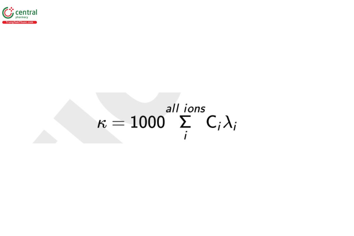
where κ is the conductivity (S/cm), C is the concentration of chemical ion i (mole/L), and λ is the specific conductance of ion i (S · cm2/mole). Though S/m is the appropriate SI unit for conductivity (i.e., the base SI units are the ampere and the meter) units of S/cm historically have been selected as the accepted unit of expression.
At low ion concentrations (typically <10−3 mole/L), the conductivity–concentration relationship is linear and valid because λ is constant for each ion, but there are three notable exceptions to this strict linearity and proportionality. First, at higher concentrations (approximately 10−3 to 1 mole/L) small negative deviations from linearity (<5% per decade) arise because of the decrease in λ for each ion, and the negative deviations vary from ion to ion. Second, at higher concentrations for weak acids and bases the extent of dissociation into ions decreases depending on their dissociation constants. As the concentration of a weak acid/base increases, the conjugate cation/anion concentration increases as the square root of the acid/base concentration. Third, at high concentrations (>20%) of certain strong acids such as HNO3 and H2SO4, the negative deviations persist, and, in some cases, the conductivity decreases with increasing concentration. The conductivity of high-concentration acid systems is well documented.
Another variable that influences conductivity measurements is the fluid temperature. A stricter expression of Equation 1 is shown below as Equation 2:
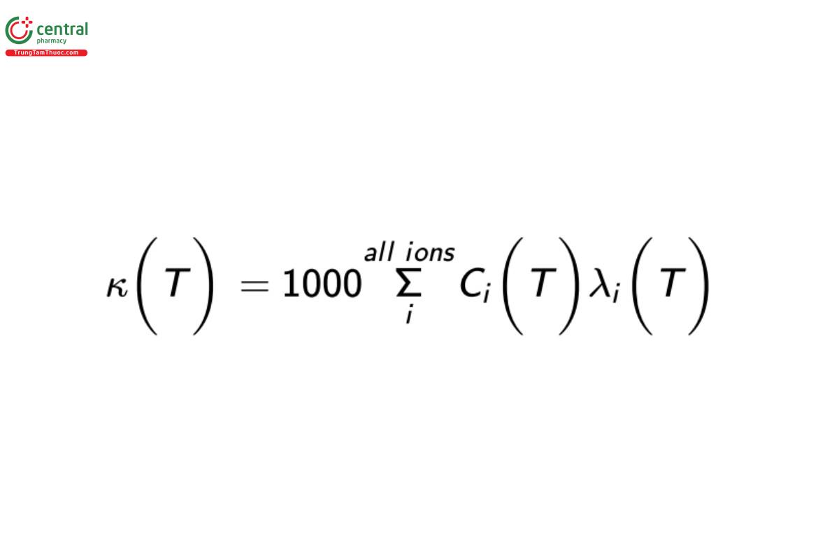
where the conductivity measurement, ion concentrations, and specific ion conductances are temperature (T) dependent. As fluid temperature increases, the ions become more efficient electrical conduits, making this physicochemical phenomenon the predominant reason for the temperature-compensation requirement when testing conductive fluids. The specific ion conductance of all ions increases with increasing temperature. In addition, the concentration of ions can also change as a function of temperature. For example, the auto-dissociation constant of water, Kw, increases with temperature from 0° to 100°, resulting in the increased production of H+ and OH− .
Strictly speaking, it is challenging to temperature-compensate perfectly the conductivity measurement to a reference temperature unless the ionic species are well known. In many applications the ionic species are well known, and in most other cases simple assumptions make this issue less demanding. Temperature compensation is discussed in further detail in Temperature Compensation, below.
2 THEORY OF OPERATION
2.1 Alternating Current Measurement Method
Conductivity is measured by applying a voltage (or current) between two conducting electrodes and measuring the resistance of the fluid using Ohm's Law. Various methods are used to apply the voltage/current, but all have the property of using an alternating voltage/current (AC) in order to minimize polarization (or collection of ions) at the electrodes or any electrolytic reaction. If a direct voltage/current (DC) is used, then the positive ions will collect at the negative electrode, and negative ions will collect at the positive electrode. The collection of ions at the electrode prevents the flow of current and adversely affects the accuracy and stability of the conductivity measurement. The measuring frequency of the AC signal depends on the technology and can range from as low as 30 Hz in low-conducting fluids and up to 4 kHz in highly conductive fluids. The specific frequencies are not relevant to operation of the system because the drive frequency is embedded in the instrument's measurement systems and is integrally linked to the supplier's measurement technology. This chapter does not seek to evaluate different measurement technologies because they are usually microprocessor-controlled systems and are proprietary.
The two-electrode AC measurement technique is valid for use with all concentrations of ionic species ranging from acids and bases (high conductivity) to Water for Injection and Purified Water (low conductivity) and even to organic, weakly ionic species such as alcohols and glycols. The measurement can be sensitive to ion concentrations as low as 0.05 µg/L. For high ion concentrations, analysts can use an alternative 4-electrode measurement method in which the current is applied between two of the electrodes and the voltage is measured between the two other electrodes. Ions are driven to the current electrodes while the voltage electrodes make the measurement with limited polarization effects.
2.2 Units of Expression
There is no difference in the physical measurement of conductivity and resistivity—they are multiplicative inverse measurements of each other. Therefore, if one measurement is known, then the other value is readily calculated by taking the reciprocal of the numerical value and the units. There is also no difference in the instrumentation or the sensors. The only difference is how the measured value is reported or displayed for the convenience of the analyst. For example, 18.2 MΩ · cm = 0.0550 µS/cm and 5.23 kΩ · cm = 0.191 mS/cm = 191 µS/cm.
Although the proper SI units are Ω · m or S/m, the traditionally used units are Ω · cm or S/cm.
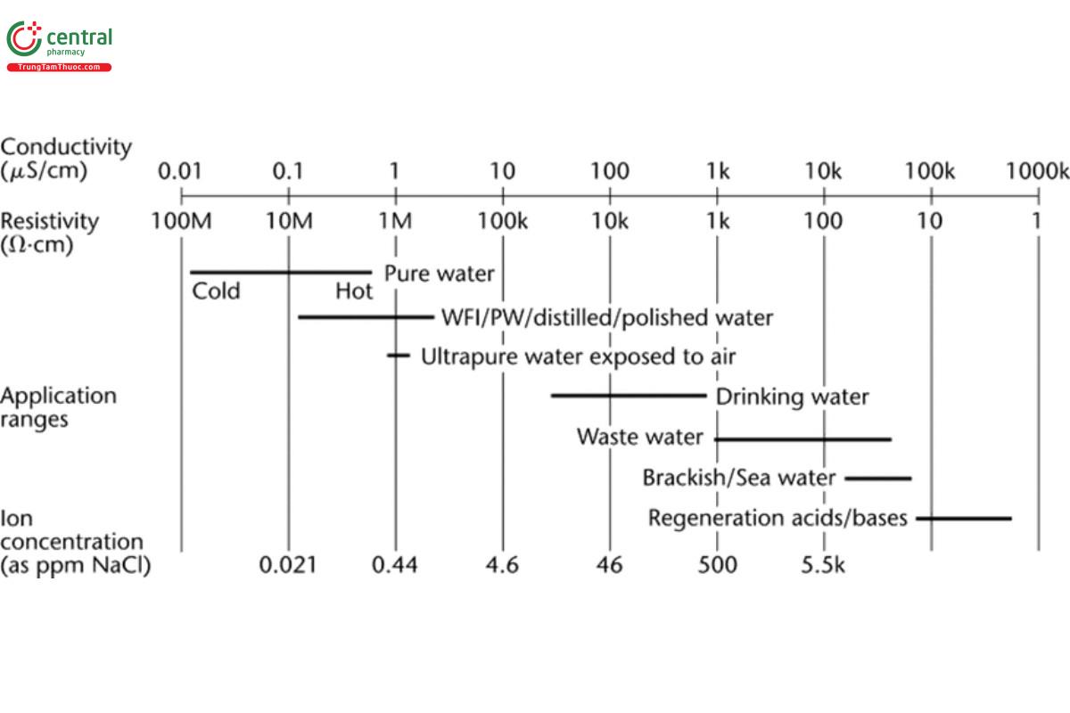
Figure 1 shows relationships among conductivity, resistivity, and some example process fluids of various grades of purity. The conductivity of fluids in pharmaceutical systems varies over approximately 8 orders of magnitude. In high-purity water systems, the quantity of ions present in Purified Water or Water for Injection is very low, resulting in a conductivity <5 µS/cm and often approaching 0.055 µS/cm or less. [NOTE—The conductivity of the purest waters at temperatures less than 25° is less than 0.055 µS/cm.] In drinking waters, the conductivity may vary from 30 to 2000 µS/cm. In chromatographic separations, the conductivity of the eluent may vary from 0.1 to 100 mS/cm. For hot concentrated acids, the conductivity may be as high as 1 S/cm.
2.3 Cell Constant Determination
The purpose of the sensor's cell constant is to normalize the conductance/resistance measurement for the geometrical construction of two electrodes. When two electrodes are placed in a conducting fluid and a voltage is applied to them, there is a conductance (resistance) between the electrodes. If the electrodes are placed farther apart, the conductance decreases (resistance increases). If the area of the electrodes increases, then the conductance increases (resistance decreases). In both cases, the ion concentrations between the electrodes do not change, but the geometrical construction of the sensor (cell constant) alters the measured conductance (resistance). The conductivity of a solution (κ, S/cm) is related to the conductance, G (siemens) according to Equation 3:
κ = G × (d/A) = G × θ
where A is the area of the conducting electrodes (cm2) and d is the distance between the electrodes (cm). The other common unit of expression is the reciprocal of conductivity, or resistivity, ρ (Ω · cm), as described in Equation 4:
ρ = 1/κ = 1/(G × θ) = R/θ
where R is the resistance of the fluid between the electrodes (1 Ω = 1 S−1). The geometrical ratio, d/A (or θ), is known as the cell constant (cm−1) of the sensor.
Determination of the cell constant by the direct measurement of d and A is impractical because of variations in the geometrical configurations and the nonuniformity of the electric field between the electrodes. Practically, the cell constant is determined by the measurement of aqueous solutions of known conductivity. See Calibration below.
2.4 Temperature Compensation
Temperature compensation is a typical requirement for most conductivity measurements, although there are exceptions such as those contained in Water Conductivity 〈645〉. As noted previously, the conductivity of a fluid is related to its temperature. As the temperature increases, ions become more mobile and the conductivity increases. The effect of temperature depends on the type and concentration of the ion, but for most solutions >10 µS/cm the impact of temperature is in the range of 1.9%/° to 2.2%/°. For strong acids, this may be as low as 1.5%/°. For high-purity compendial waters, the temperature coefficient varies from 2.0%/° to 7.5%/° depending on the temperature and purity of the water. For each case described here, some knowledge of the type of impurity is needed in order to ensure adequate temperature compensation. If the conductivity vs. temperature function is linear and the temperature coefficient is constant, the equation that relates the compensated conductivity to the non–temperature-compensated conductivity is described in Equation 5:
κ25 = κT / [1+α(T−25)]
where T is the measured temperature, κ25 is the conductivity compensated to 25°, κT is the conductivity at T, and α is 0.02 for a temperature coefficient of 2%/°.
Most conductivity measurement systems measure the uncompensated conductivity/resistivity and the temperature, and the temperature- compensated conductivity is determined via mathematical algorithms (e.g., by application of Equation 5) in the microprocessor of the transmitter. Depending on the application and knowledge of the content of the fluid, different compensation algorithms may be available. For most process control applications, temperature compensation is recommended because when the uncompensated conductivity changes it is impractical to distinguish whether this change is caused by temperature fluctuation or a change in ionic content. Temperature compensation allows the analyst to distinguish between changes in temperature and ionic content. Compensation to a reference temperature of 25° is standard practice, but some methods specify temperature compensation to 20°.
Most conductivity sensors have temperature devices such as a platinum RTD (resistance temperature device) or NTC (negative temperature coefficient) thermistor embedded inside the sensor, although external temperature measurement is possible.
3 OPERATIONAL CONSIDERATIONS
3.1 System Components
The usual components of a conductivity measurement system are the sensor, the transmitter, and the cable that connects the sensor to the transmitter. The sensor is the device that is in direct contact with the fluid. The sensor consists of the electrodes, usually an embedded temperature device, and a process connection (e.g., a tri-clamp if the sensor is intended for in-process sanitary applications). Traditionally, sensors are passive electromechanical devices and do not contain measurement circuitry.The transmitter is the device that measures the resistance between the sensor's electrodes, measures the resistance of the temperature-measuring device, converts the resistance measurement to a conductivity (or resistivity), and performs temperature corrections to compensate the signal to a reference temperature. The cable connects the sensor to the transmitter. In process control or monitoring systems, the cable allows the sensor to be attached to a process tank or pipe, and the transmitter can be located at a control panel or other remote location, if necessary. The distance between the sensor and the transmitter may affect measurement accuracy caused by the added cable resistance and the susceptibility of the cable to external noise. Therefore, this distance should be considered during selection of the measurement system. In some conductivity measurement systems, the measurement circuitry is directly attached to the conductivity sensor, allowing digital transfer of the measurement results to a remote display at greater distances than traditional measuring systems with wire transmission of analog signals.
3.2 Materials of Construction
The sensor's materials of construction are critical when the sensor may be in contact directly or indirectly with the product. For most laboratory applications, materials of construction are less critical. All sensors contain measuring electrodes and an insulating material between the electrodes. Technically, the only requirements are for electrodes to be electrically conducting and to be able to withstand the physical and chemical environment. Electrodes can be made of various grades of stainless steel, titanium, graphite, and many other metals. The insulating materials must isolate the electrodes from each other so that only the fluid conductivity is measured. Insulating materials are usually made of an inert polymer, epoxy, or ceramic.
If the sensor is connected directly to a process vessel or the piping system, then the sensor's materials of construction must meet the thermal and hydraulic (pressure) requirements of the process system. The sensor must have a proper process connection to the vessel/piping. Depending on the application, the sensor also may be required to meet biological compatibility, material, or hygienic design requirements. The sensor must not degrade during installation and operation. The sensor must be able to withstand any other processes that the system may encounter such as clean-in-place or steam-in-place processes. Otherwise analysts may need to remove the sensor from the process. When immersion of the sensor into the process places the process at risk, the sensor should be installed in a housing that is attached to the sidestream. In this case, a fraction of process fluid flows to the housing and sensor and then to drain. This allows indirect measurement of the process fluid without harm to the process or product.
If the conductivity measurement is performed off-line, e.g., in a laboratory environment, then the operating considerations are reduced because the thermal, hydraulic, and other product-contact concerns are reduced or eliminated.
4 CALIBRATION
The process of calibrating a complete conductivity measurement system generally consists of three parts. First, the transmitter's electronic circuitry is calibrated. Second, the temperature sensor device is calibrated. Third, the cell constant of the conductivity sensor is determined. In each case, verification may precede any calibration to determine if an adjustment is necessary. In most cases for microprocessor-controlled instrumentation, there is no formal mechanical or electronic adjustment of these subsystems. Instead, these adjustments are usually made in software-controlled calibrations that are computed automatically by the transmitter.
A calibrated transmitter should be used in order to calibrate the temperature sensor and cell constant. The transmitter used to calibrate the temperature sensor and cell constant can be the transmitter used in normal operation, or another transmitter can be used instead. Because of differences in a supplier's wiring and electronic compatibility, it may be necessary to use the same type of transmitter.
As is the case for all instrument-based methods, calibration frequency depends on many factors. Depending on the type of conductivity sensor and transmitter, calibration cycles vary from weekly to annually based on manufacturers' recommendations, historical performance of the instrumentation, internal requirements, and the criticality of the application. For robust process instrumentation, typical calibration cycles for the electronics and the sensor take place approximately every 12 months. When the sensor's cell constant can be altered by the fluid or the process conditions, more frequent calibration may be needed.
4.1 Instrument Calibration
The transmitter's electronic circuitry is calibrated by disconnecting the sensor from the transmitter, connecting precision resistors (resistors of known value) to the transmitter, and comparing the traceable resistance value to the measured resistance value. The resistance values should be traceable to a competent national authority. The resistance values should be selected so that they are in the range of (1) the measurement capability of the transmitter, and (2) the resistance that will be measured during operation. The transmitter may have multiple circuits internally, so verification of the appropriate circuit (or all circuits) and measurement range is necessary. Comparison of the measured resistance to the actual resistance verifies if the transmitter is properly calibrated. The resulting difference must be within a predetermined x1 % of the actual resistance, where x1 indicates the desired conductivity circuit electronics performance. Typical conductivity circuit electronics performance is usually in the range of 2% or less of the target value. Otherwise, adjustment of the resistance measurement circuit is recommended.
An example of the transmitter's measurement electronics calibration process follows: A typical operating range for a clean-in-place process may be in the 50 to 75 mS/cm range. A sensor with a cell constant of 5.0 cm−1 is used in this example. Based on Equation 4, this requires a measuring resistance of 67 to 100 Ω. To verify the conductivity measuring circuit during calibration, analysts should use a resistor(s) with a traceable value in or near this range. When compendial waters are used, typical measurements are in the range of 1 to 20 MΩ · cm and use sensors with a cell constant of 0.1 cm−1. This computes to a resistance of 0.1 to 2 MΩ. Resistors with a traceable value in this range should be used. If the recorded values are within the range of the pre-established acceptance criteria (x %), then adjustment is not required.
4.2 Temperature Measurement and Sensor Calibration
If a temperature measurement circuit is integrated into the transmitter and is used as part of the measurement system, then verification and/or calibration of this circuit is required. Depending on the type of temperature device in the sensor, an appropriate signal source (e.g., resistance) should be input to the transmitter. Comparison of the measured temperature and the simulated temperature verifies if the temperature measurement circuit is properly calibrated. The resulting difference must be within x2° of the simulated temperature where x2 indicates the desired temperature circuit electronics performance. Typical temperature circuit electronics performance usually is in the range of ±1° or less. If the difference meets the pre-established acceptance criteria, no further action is required. Otherwise, adjustment of the temperature measurement circuit is recommended using the protocol in the transmitter's calibration function.
If a temperature sensor is integrated into the conductivity sensor, the temperature sensor can be calibrated by comparison of the sensor's temperature measurement to a reference system. This is accomplished by immersing the process and reference sensors in the same fluid. The reference system can be another traceable temperature measurement device or a fluid system of known temperature such as boiling water (corrected for elevation, if this degree of accuracy is necessary) or an ice-water bath.
The accuracy of the calibration is related to the accuracy of the reference sensor, the thermal homogeneity of the fluid, and the elimination or reduction of any artifacts that can negatively influence accuracy. For example, if the sensor is not fully immersed in the fluid, thermal conduction from the ambient environment can alter the temperature measurement. Careful insulation of the sensor from the ambient environment may improve the accuracy of temperature measurements, particularly if the reference temperature is substantially different than the ambient temperature.
Comparison of the measured temperature and the reference temperature verifies if the temperature sensor is properly calibrated. The resulting difference must be within x3° of the reference temperature where x3 indicates the desired temperature accuracy that is required for the process. Temperature sensor accuracy is usually in the range of ±2° or less. If the difference meets the pre-established acceptance criteria, no further action is required. Otherwise, adjustment of the temperature sensor calibration factors is recommended using the protocol in the sensor's calibration function.
4.3 Cell Constant Calibration
The cell constant of the sensor is determined by comparing the conductivity measurement of the system to that from a reference conductivity system and adjusting the cell constant. Place the sensor in a reference solution of known conductivity whose value is traceable to a competent authority. The reference solution can be a solution of known conductivity in one of three ways:
1. The solution can be produced according to a standard method that is traceable to a competent authority. One method is to prepare one of the solutions listed in ASTM D1125. Another method is to use ultra-pure deionized water with no exposure to air whose conductivity is known.
2. The solution can be procured from a third-party supplier with traceability to an acceptable authority. Cell constant calibration should be performed in the recommended temperature range of the reference solution.
3. The solution can be any fluid whose conductivity is known by measurement from an alternative and traceable reference conductivity measurement system.
In all three cases, regardless of the type of calibration methodology, there are some fundamental requirements. The sensor's cell constant should be calibrated at a conductivity that is in the measurement range of the measuring system. For example, if the system is designed to measure in the 0–100 µS/cm range, then use of a 1000 µS/cm reference solution is not advised.
Because the cell constant is a geometrical property of the sensor and is a constant, the determination and/or calibration of the cell constant does not need to be in the operational range of the pharmaceutical process as long as the conductivity is in the operational range of the measurement system. Also, because the cell constant is a geometrical property of the sensor, a single-point calibration typically is sufficient. In some applications, a 2-point calibration can provide improved accuracy at very high conductivity. Depending on the reference solution, cell constant calibration can be performed with or without temperature compensation. For reference solutions exceeding 10 µS/cm, if temperature compensation is needed a temperature coefficient (α) of 2%/° is sufficient over the range of 25 ± 10° unless otherwise specified.
Adjustment of the cell constant is recommended if the difference between the measured and reference conductivity exceeds x4 % of the reference conductivity where x4 indicates the conductivity accuracy that is required for the process. Typical conductivity accuracy is 5% or less. If the accuracy measurement meets the pre-established acceptance criteria, no further action is required. Otherwise, adjustment of the sensor's cell constant is recommended using the protocol within the sensor's calibration function.
5 OPERATION
5.1 In-line, At-line, and Off-line Measurements
Depending on the application, in-line, at-line, and off-line measurements have specific universal requirements. Each has advantages and disadvantages depending on the application, but the fundamental technologies (AC measurement) supporting each measurement type are constant. The primary differences between the in-line/at-line and the off-line systems are sensor features related to process robustness and transmitter features related to output functions, external communication capabilities, and system installation costs. In-line and at-line systems have added benefits of real-time measurements and continuous data acquisition. They also have added one-time electrical and plumbing installation costs, and the instrumentation is fixed in a specific location for a single process and purpose. Also, sample is diverted to drain, resulting in product loss. Note that the fluid flow velocity should be high enough that the velocity does not affect the measurement. Off-line (or laboratory-based) systems have the benefit of measuring many sample types under controlled conditions. Off-line batch testing has added costs associated with cleaning containers and collecting samples as well as risks of sample contamination.
In-line conductivity measurements are suitable when the following conditions are met: (1) there is a need for or value of real-time, continuous data; (2) the sensor and the application/fluid are compatible and cause no harm to each other; and (3) atmospheric contamination must be avoided. In these cases, continuous process control, decisions, and intervention are available.
At-line (or sidestream) conductivity measurements are used when the following conditions are met: (1) a need exists for or value of real- time, continuous data; (2) the sensor and the application are compatible with each other; (3) the sensor can cause harm to the application and/or fluid; and (4) atmospheric contamination must be avoided. In such cases the measurement is made by delivering the sample from the tank/piping using hydraulic pressure (flow) to the conductivity sensor, and the fluid passes through the sensor and goes to drain. In these cases, continuous process control, decisions, and intervention are available and have no affect on product or application. The only requirement is positive pressure upstream from the sensor to prevent backstreaming of the sample fluid back into the process.
Off-line conductivity measurements are used when the following conditions are met: (1) no need exists for or value of real-time or continuous data; (2) the sensor and the application are compatible with each other, but the sensor can cause harm to the application and/or fluid; and (3) sampling needs are infrequent or are needed on a limited basis.
5.2 Sample Preparation and Off-line Measurement
When performing off-line measurements, analysts must ensure that the container used to collect the fluid sample(s) is sufficiently clean so that the container does not alter the result. Collect an amount of fluid needed for rinsing and measuring. For samples such as Purified Water where the analysis can be affected by gasses, containers should be filled completely to reduce headspace. The volume of fluid needed to make a measurement depends on the design of the sensor and can range from <10 mL to 1 L. Transfer a portion of the sample fluid to the clean measuring container to rinse the container walls. Discard the fluid. The sample container also can be used as the measuring vessel.
The sensor should be rinsed with a suitable quality of water or other appropriate fluid before use so the measurement is not affected and then rinsed at least once with the solution to be measured, which then is discarded. This rinse with sample solution removes any residue or fluids with which the conductivity sensor previously was in contact. The exact procedure varies depending on the solution tested. For example, when testing very low conductivity samples such as Purified Water, analysts must do more rinsing to remove any remaining residue from the sensor. Maximum holding time, temperature, and container type must be controlled for some low-conductivity samples, e.g., high- purity waters, because of the potential impact of ionic leachables from certain containers.
Transfer the fluid to the measuring container, immerse the sensor into the fluid, and ensure acceptable clearance around the sensor's measurement area. Stir or agitate the sample to prevent bubbles from attaching to the electrodes and disturbing the measurement. If a temperature-compensated measurement is used, then select the appropriate temperature-compensation algorithm in the transmitter, and adjust the sample temperature to the recommended range, if necessary, using an appropriate temperature bath. Otherwise, disable the temperature compensation. Verify that the temperature is sufficiently stable (<0.25° change per min), and record the conductivity reading and the temperature, if necessary.
5.3 In-line Measurement
For in-line testing, the sensor is installed into the process piping or vessel. The orientation of the sensor relative to the flow of the fluid is critical to ensure that (1) particles and sediment do not collect between the measuring electrodes, and (2) no air pockets are trapped between the measuring electrodes. Both factors can adversely affect the measurement accuracy. Depending on the electrode design, manufacturers usually provide recommendations. Ensure the sensor is clean before installation.
After the sensor is immersed in the closed process, such as a piping system or tank, the sensor does not require removal and cleaning before a measurement. If a temperature-compensated measurement is used, then select the appropriate temperature-compensation algorithm. Otherwise, disable the temperature compensation. Although temperature stability is desirable, it may not be possible depending on the temperature control of the process. Record the conductivity reading and the temperature, if necessary.
5.4 At-line Measurement
For at-line testing, a piece of tubing is used to connect the process vessel/piping to the sensor and its housing. The tubing should be cleaned or flushed with an appropriate cleaning agent to remove any impurities that could alter the conductivity measurement. The tubing can be made of metal or plastic depending on the application and chemical compatibility. Installation of the sensor into a housing permits fluid to be directed into the sensor and then to drain. Installation considerations are similar to those for in-line installations. Ensure the sensor and housing are clean before installation.
After the sensor and housing are connected to the sidestream, the sensor does not require removal and cleaning before a measurement. If a temperature-compensated measurement is used, then select the appropriate temperature-compensation algorithm. Otherwise, disable the temperature compensation. Although temperature stability is desirable, it may not be possible depending on the temperature control of the process. Record the conductivity reading and the temperature, if necessary.
5.5 Other Considerations
In all cases mentioned above, the use of abrasive materials to clean the sensor typically is discouraged. Two reasons to avoid abrasive cleaning materials are that (1) the passive layer of stainless steel sensors (when used) can be destroyed, and (2) the surface of the measurement area can affect the measurement accuracy. For these reasons, the use of appropriate chemically compatible fluids is preferred instead of mechanical methods for cleaning.
Unlike the requirements for many electrochemical measurements, the need for flowing, circulating, or agitating fluid is not a fundamental requirement for a conductivity measurement. In general, there is no difference in the conductivity measurement of a static or a flowing sample, but two conditions must be met for static samples: First, bubbles cannot be allowed to collect on the measuring area of the electrodes because they can interfere with the flow of current conductivity measurement. Second, if sample homogeneity is affected by the lack of agitation or circulation, then the conductivity measurement may not represent the conductivity of the bulk fluid.
In all cases, the installation of the sensor should take into consideration wall effects from the vessel, piping, or laboratory container. If the proximity of the wall interferes with the electromagnetic field for the conductivity measurement, then the measurement could be positively or negatively altered. Some 2-electrode sensor designs, such as coaxial concentric electrodes, are not affected by nearby objects. The sensor's installation instructions may indicate if this must be considered.
If unstable conductivity readings are observed, some common causes could be inadequate grounding of the water system, electronic noise from pumps and other high-frequency generators, or internal leakage of the sensor. Various diagnostic approaches are available and can help identify the cause.
