Tensile Strength
If you find any inaccurate information, please let us know by providing your feedback here


Tóm tắt nội dung
This article is compiled based on the United States Pharmacopeia (USP) – 2025 Edition
Issued and maintained by the United States Pharmacopeial Convention (USP)
DOWNLOAD PDF HERE
Change to read:
Testing devices (USP 1-Dec-2019) for measurement of tensile strength used in the United States may be calibrated in the English units of measure. The following directions are given in metric units with the understanding that the corresponding English equivalents may be used.
Change to read:
1 SURGICAL SUTURE
Determine the tensile strength of surgical suture on a motor-driven tensile strength testing machine having suitable clamps for holding the specimen firmly and using (USP 1-Dec-2019) the principle of constant rate of elongation of specimen, as described below. The apparatus has two clamps for holding the strand. One of these clamps is mobile. The clamps are designed so that the strand being tested can be attached without any possibility of slipping. Gauge length is defined as the interior distance between the two clamps. For gauge lengths of 125–200 mm, the mobile clamp is driven at a constant rate of elongation of 30 ± 5 cm/min. For gauge lengths of less than 125 mm, the rate of elongation per minute is adjusted to equal 2 times the gauge length per minute. For example, a 5-cm gauge length has a rate of elongation of 10 cm/min.
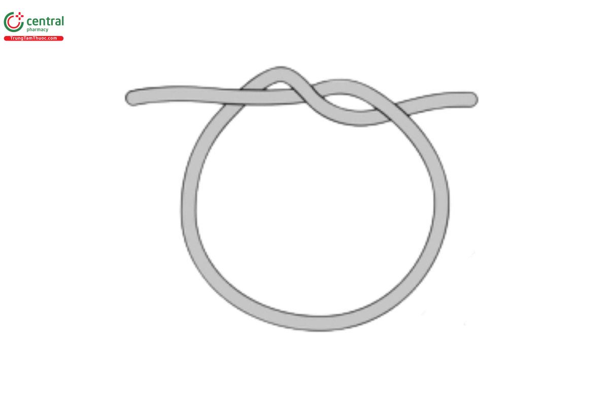
Determine the tensile strength of the suture, whether packaged in dry form or in fluid, promptly after removal from the container, without prior drying or conditioning. Except where straight pull (no knot required) is indicated in the suture monographs, tie the test suture into a simple knot formed by placing one end of a strand held in the right hand over the other end held in the left hand. Then pass one end over the strand and through the loop that is formed (see Figure 1), and pull the knot tight so as not to affect the integrity of the suture.
Place the specimen in the testing device with the knot approximately midway between the clamps. (USP 1-Dec-2019) Attach one free (USP
1-Dec-2019) end of the suture to the clamp at the load end of the machine, pass the other free (USP 1-Dec-2019) end through the opposite clamp, applying sufficient tension so that the specimen is taut between the clamps, and engage the second clamp. Perform as many breaks as are specified in the individual monograph. If the break occurs at or in (USP 1-Dec-2019) the clamp, discard and replace with an additional pull with a new test suture. The discarded result should be noted and recorded, but not included in the averaging of the results.
For suture devices that are not knotted, a straight pull should be used for testing. Strength should be compared to the knot tie values for labeled sizes in the monograph table. (USP 1-Dec-2019)
Add the following:
2 BARBED SUTURES
Barbed suture type devices that do not require the use of knots in their application should not be tested for USP knot-pull tensile strength by the use of knots. The alterations to the surface (i.e., barbing) of these devices would lead to testing bias were a USP knot pull be applied to the device. For these types of devices, refer to the manufacturer’s specifications with respect to the USP size designation identified and perform straight pull testing accordingly. Compare results generated to the identified USP size knot-pull specifications. (USP 1-Dec-2019)
Change to read:
3 TEXTILE FABRICS AND FILMS
Determine the tensile strength of textile fabrics, including adhesive tape, on a constant-speed or pendulum type of testing device (USP 1-Dec-2019) of the following general description.
The clamps for holding the specimen are smooth, flat, parallel jaws that are NLT 25 mm in length in the dimension parallel to the direction of application of the load. When the width of the strip being tested does not exceed 19 mm, the jaws of the clamp should be at least 25 mm wide. If the width of the strip is greater than 19 mm and NMT 44 mm, the width of the jaws of the clamp should be at least 50 mm. If the width of the specimen is greater than 44 mm, cut a 25-mm strip, and use a clamp with jaws NLT 50 mm wide. Round all edges that might have a cutting action on the specimen to a radius of 0.4 mm. The jaws are 76.2 mm apart at the beginning of the test, and they separate at the rate of 30.5 cm ± 13 mm/min. The machine is of such capacity that when the break occurs, the deviation of the pendulum from the vertical is 9° - 45°.
