Temperature Mapping for the Qualification of Storage Areas
If you find any inaccurate information, please let us know by providing your feedback here

Tóm tắt nội dung
This article is compiled based on the United States Pharmacopeia (USP) – 2025 Edition
Issued and maintained by the United States Pharmacopeial Convention (USP)
1 INTRODUCTION
The extent of physicochemical degradation of drug products depends on factors such as product stability to include how a product is stored. Storage and holding areas need to maintain labeled temperature ranges to ensure product efficacy and expiry. Many factors impact the ability of a drug storage area to maintain acceptable temperature ranges (see Packaging and Storage Requirements 〈659〉), including airflow, heating and air conditioning, wall and ceiling insulation, doors, traffic (e.g., frequency and time that doors are open), geography, and orientation of the physical structure.
The ability of a storage area to maintain temperature ranges may need to be evaluated to determine risk areas (areas unable to maintain temperature ranges) and the effectiveness of mitigation strategies implemented to reduce risks. Temperature excursion should be evaluated per 〈659〉, Risks and Mitigation Strategies for the Storage and Transportation of Finished Drug Products 〈1079〉 and Mean Kinetic Temperature in the Evaluation of Temperature Excursions During Storage and Transportation of Drug Products 〈1079.2〉, as discussed in two recently published USP Stimuli articles (1,2).
A technique used to evaluate the effectiveness of drug product storage areas in maintaining temperature is referred to as temperature mapping. Proper use of temperature mapping can help determine whether storage areas can maintain the appropriate temperatures as well as identify any areas that may require mitigation. The results of temperature mapping will also determine continuous monitoring device placement.
2 SCOPE
This chapter will focus on the qualification of storage areas to maintain temperature and does not cover other important storage requirements required for drugs (see 〈1079〉 or applicable laws regarding security, pest control, training, etc.).
This chapter applies to every link in the supply chain from the manufacturer through any entity that has a role in the storage or holding of finished drug product, with the sole exception of the patient. This chapter does not include shipping systems or transportation. Some examples are:
- Manufacturers of drug products, radiopharmaceuticals, biological products, and biotechnological products
- Repackaging operations in which the product may be owned by a company other than the primary manufacturer
- Healthcare providers and institutions such as hospitals; outpatient, ambulatory, and urgent care centers; home health providers; vaccine clinics; emergency departments; medical, dental, and veterinary offices
- Pharmacies, including but not limited to retail, infusion and compounding (sterile and nonsterile), specialty, mail order, hospital, nursing home, and hospice
- Importers and exporters
- Wholesale distributors
- Third-party logistics providers, brokers, freight forwarders, consolidators, and other organizations involved in storage or holding service
Manufacturers of active pharmaceutical ingredients, excipients, medical devices (with the exception of drug combination devices), and dietary supplements are not within the scope of this chapter. However, the principles presented in this chapter may be useful for materials other than finished drug products.
3 EVALUATE PRODUCT STORAGE AREA
The physical layout of each storage area must be obtained, to include:
- Dimensions, including height, ceiling height changes and/or variations, walls, and wall openings (e.g., loading docks, passageways, and personnel doors). Additionally, the type of openings should be identified (e.g., automatic sliding doors, revolving doors, push/pull doors, etc.) as these can uniquely impact air flow and temperature excursions.
- Location of heating, ventilation, and air conditioning (HVAC) equipment, space heaters, and air conditioners
- Sun-facing walls
- Geographic location of the area being mapped
- Airflow inside of the storage location
- Temperature variability outside of the storage location
- Workflow variation and movement of equipment (weekday versus weekend)
- Loading volume or storage patterns of product
- Equipment capabilities (e.g., defrost mode, cycle mode)
- Standard operating procedures (SOPs) (e.g., operational workflows such as working hours, times when doors are open, assembly, reworking, packing, and placement or movement of equipment)
3.1 Temperature Monitoring Device Probe Placement
The next step is to establish the number of temperature probes to be used following the organization’s policy, government requirements, or a rationale to meet such standards. This is suggested guidance and should not be interpreted as a requirement or standard that supersedes an organization’s SOPs or applicable laws. Areas separated by a demising wall, doors, different ceiling height, or floor layout should be considered separate areas. Other considerations include, but are not limited to the placement of lights, heaters, doors, storage racking, and floor and/or pallet staging. A rationale should be developed for probe placement to include applicable governing laws or standards that an organization references in their policy and procedures [e.g., World Health Organization (WHO) Supplement 8 states that probe placement covering length and width may include placement every 5 to 10 m]. However, examples in this chapter can be used to determine if a storage area is capable of maintaining desired temperatures. Organizations may increase the number of probes for extremely large storage areas. Example floor plans showing variations in storage areas are provided below, ranging from smaller storage areas to larger storage areas, where:
<2 m3 (70.5 ft3) = 10 probes
2 m3 to 20 m3 (70 to 706 ft) = 16 probes
>20 m3 (706 ft3) = 28 probes
H = high probe (highest level product is stocked); L = low probe (lowest level product is stocked); T = probe placed directly next to the thermostat that controls the temperature in this area. Reach in freezers may have two or more separate storage areas with doors to access; all these areas must be evaluated.
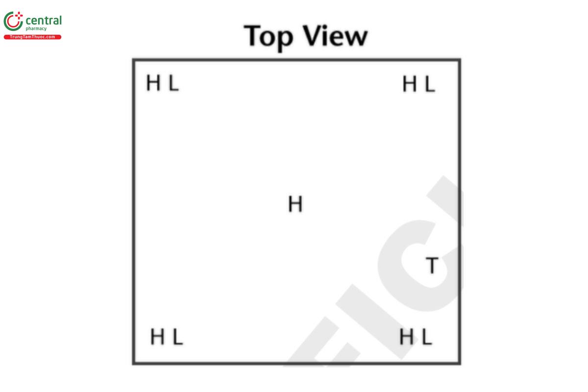
3.2 Small Reach In Freezer or Refrigerator Unit
Example: 0.61 × 0.61 × 0.61 m (2 × 2 × 2 ft) = 0.227 m3(8 ft3) (approximate due to rounding errors).
H = high probe (highest level product is stocked); L = low probe (lowest level product is stocked); T = probe placed directly next to the thermostat that controls the temperature in this area. Reach in freezers may have two or more separate storage areas with doors to access; all these areas must be evaluated.
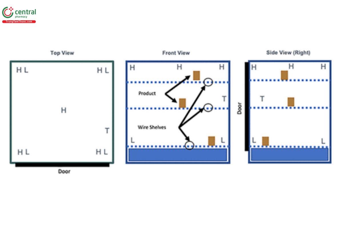
3.3 Small Reach In Freezer or Refrigerator Unit
Example: split-level. H = high probe (highest level product is stocked); L = low probe (lowest level product is stocked); T = probe placed directly next to the thermostat that controls the temperature in this area. Reach in freezers may have two or more separate storage areas with doors to access; all these areas must be evaluated.
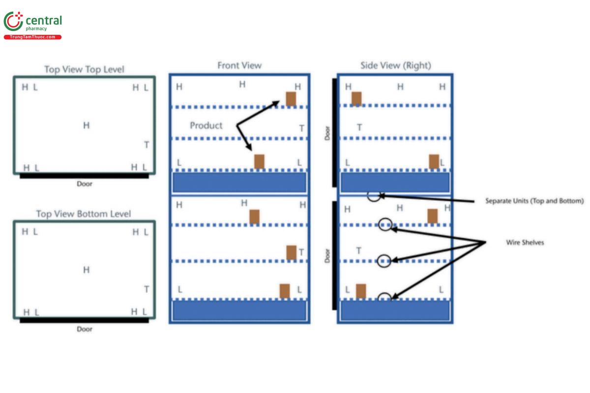
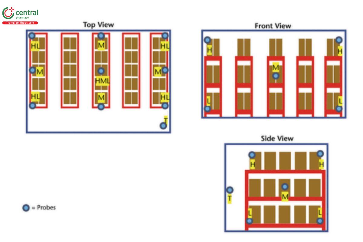
3.4 Small Walk-In Unit
Example: 2.4 × 3 × 2.4 m (7.87 × 9.84 × 7.87 ft) = 17.28 m3 (609.4 ft3) (approximate due to rounding errors) H = high probe (highest level product is stocked); M = mid probe (middle level product is stocked); L = low probe (lowest level product is stocked); T = probe placed directly next to the thermostat that controls the temperature in this area.
3.5 Small Walk- In Unit
Example: 2.4 × 3 × 2.4 m (7.87 × 9.84 × 7.87 ft) = 17.28 m3 (609.4 ft3) (approximate due to rounding errors). H = high probe (highest level product is stocked); M = mid probe (middle level product is stocked); L = low probe (lowest level product is stocked); T = probe placed directly next to the thermostat that controls the temperature in this area.
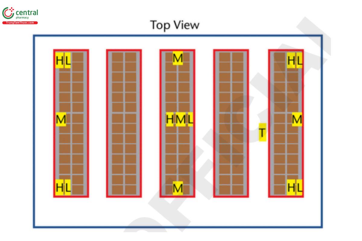
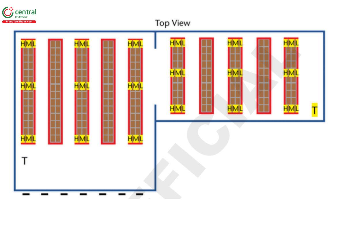
3.6 Large Storage Area/Warehouse
Example: 50 × 100 × 10 m (164 × 328 × 32.8 ft) 50,000 m3 (1,764,378 ft3) (approximate due to rounding errors). H = high probe (highest level product is stocked); M = mid probe (middle level product is stocked); L = low probe (lowest level product is stocked); T = probe placed directly next to the thermostat that controls the temperature in this area.
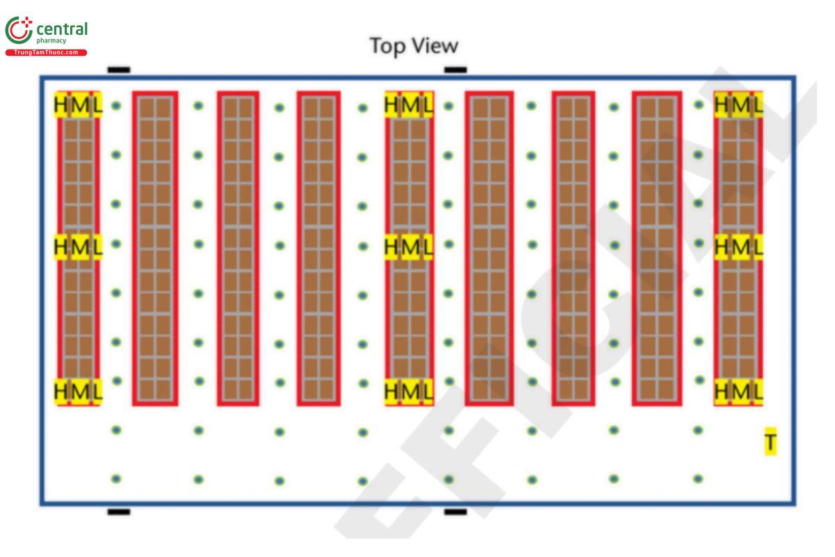
3.7 Large Storage Area/ Warehouse
Example: 50 × 100 × 10 m (164 × 328 × 32.8 ft) = 50,000 m3 (1,764,378 ft3) (approximate due to rounding errors). H = high probe (highest level product is stocked); M = mid probe (middle level product is stocked); L = low probe (lowest level product is stocked); T = probe placed directly next to the thermostat that controls the temperature in this area. NOTE: All product storage areas should be mapped, even if stored for a short time.
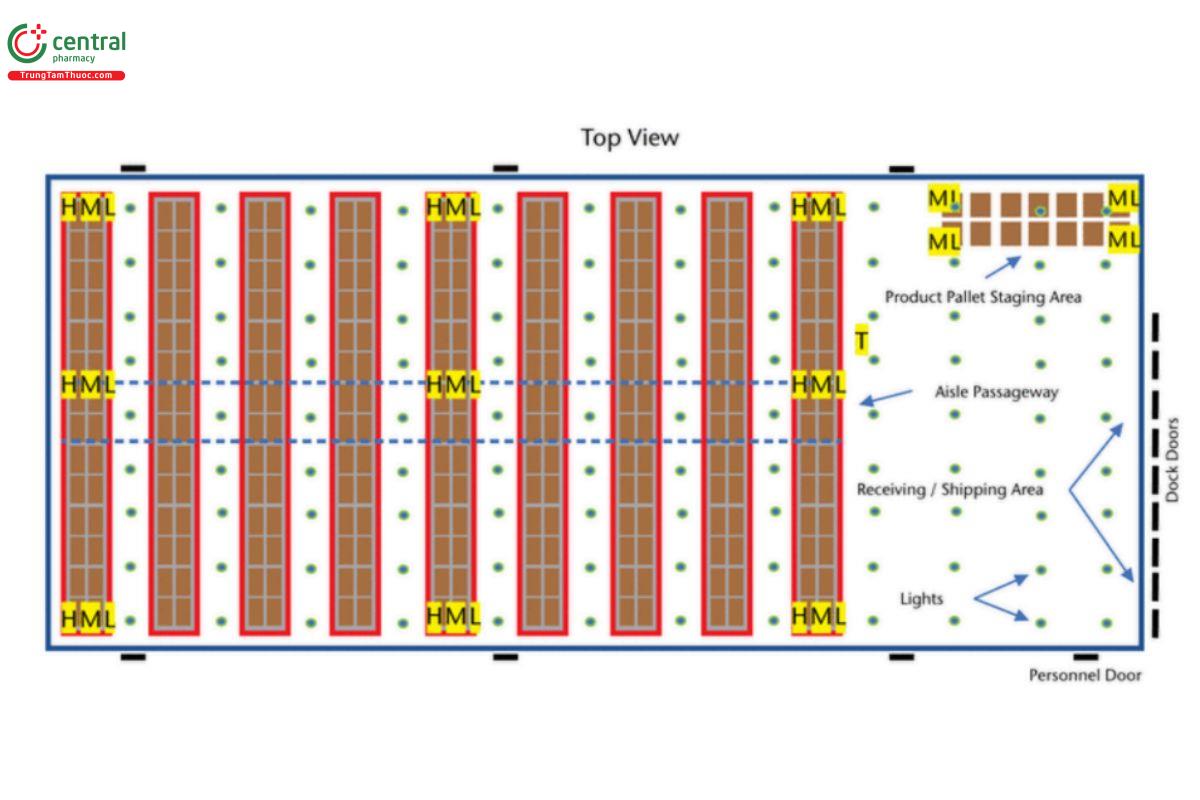
Example: large section = 80 × 1250 × 10 m (262.5 × 410.1 × 32.8 feet), plus small section = 50 × 100 × 10 m (164 × 328 × 32.8 ft) 150,000 m3 = 5,295,339 ft3 (approximate due to rounding errors). H = high probe (highest level product is stocked); M = mid probe (middle level product is stocked; L = low probe (lowest level product is stocked); T = probe placed directly next to the thermostat that controls the temperature in this area.
4 OBTAIN MONITORING DEVICES
Obtain the number of calibrated monitors for the storage range(s) that are being evaluated. It is suggested that extra monitors (5%– 10%) are obtained in the event of a mechanical failure of a monitor. See Monitoring Devices—Time, Temperature, and Humidity 〈1079.3〉.
If a refrigerator, freezer, or an ultra-low freezer is being mapped, ensure that the monitor being used is equipped with a probe wire long enough to have at least one probe inside of the area being mapped (or wireless connectivity) that can be placed next to the thermostat, so that it can be read outside of the storage area (see 5. Develop Probe Placement Map Based on Evaluation). Monitoring devices and probes should be calibrated, with appropriate documentation, before temperature mapping studies are undertaken.
Ensure devices are programmed with the correct date, time zone, and temperature ranges.
5 DEVELOP PROBE PLACEMENT MAP BASED ON EVALUATION
Probes should be placed at locations where product may be stored or staged.
All areas divided by walls, accessed with doors, or with different ceiling heights should be mapped as separate areas. Probes should be securely fastened to remain in place during the study period.
The probe placed next to the thermostat controller should have a wire lead (or wireless connectivity) to the outside of the storage area (with the exception of controlled room temperature storage) so that how the thermostat reading reacts when compared to the monitoring device can be observed.
This provides verification of the thermostat set point used during mapping that produced the results.
This can also be used during open-closed door (or power off-on) tests to see when the temperature has recovered to the normal operating range without opening the door.
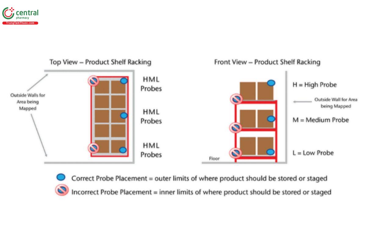
H = high probe (highest level product is stocked); M = mid probe (middle level product is stocked); L = low probe (lowest level product is stocked).
6 SCHEDULE AND EXECUTE MAPPING
- To ensure mapping is representative of the storage conditions, seasonal variations should be part of an organization mapping rationale (see 9. Frequency of Temperature Mapping).
- The duration of temperature recordings during the thermal mapping of a warehouse or cold room should capture workflow variation that may impact airflow and the resulting temperature fluctuation; for example, this process could last from 1 day to 1 week, depending on the workflow cycle.
- For rooms with redundant refrigeration systems that cycle on/off at predened frequencies for system and business redundancy purposes (e.g., system 1 is on for 8 h and then off, system 2 is on for 8 h while system 1 is off, or both system 1 and system 2 are on for 2 days), the mapping period must be long enough to capture the performance of all systems as well as the changeover periods, etc.
- If a no-load (no product) test is conducted prior to storage of the product, or if the mapping is done over a weekend or holiday without the normal personnel workflow traffic, open-door and/or close-door tests should be done to determine the impact and how much recovery time is necessary (this is especially critical, but not limited to, freezers and refrigerators).
- Load tests may be conducted with actual product or with simulated product, which should simulate the expected average thermal mass of the actual product). While this may be possible for smaller storage areas, it may not be practical for larger areas. The thermal load should never be higher than the actual product.
- If mapping is completed before product is stored in an area, mapping should be conducted again after product has been added to the area. Mapping should occur before product is stored, unless mapping is being conducted on a storage area that already has product.
- Mapping a storage area before product is added will determine if the area is capable of maintaining the product storage temperature range. Mapping after product has been placed into the storage area ensures that the product storage temperature range can be maintained with the product load’s thermal mass as well as with any airflow changes related to the product being added to the area.
- If an area is mapped during a time period when the area is not accessed (no less than 24 h), open-closed door tests and power on-off tests should be executed at the end of this initial test period.
- Areas of risk such as dock doors, sky lights, windows, etc. should be included in the mapping as a reference to understand issues at product storage spaces.
Open-Closed Door Tests
- The goal of open-closed door tests is to determine how long a door can be opened before impacting the product and how long it takes to re-equilibrate afterwards.
- The door opening length (time) and interval should be determined according to the workflow described in an SOP or a rationale. The number of repetitions and time opened should be determined by the operational use as closely as possible. For example:
1. Open for 15 s, 30 s, 1 min, and 10 min.
2. After each opening, wait until the temperature recovers before opening again.
Power On-Off Test
- The goal of power on-off tests is to test power failure. It should lead to the development of a contingency plan and the timing of when the plan should be activated. If the area being tested is on a backup power generator, this test can determine if the backup process is functional. For example:
1. Power failure—until unit goes out of range (limit).
2. Turn back on until the temperature gets back to set point.
3. Do not execute this test with product.
7 DETERMINE MITIGATION STRATEGIES (IF NEEDED)
Should probes indicate temperatures close to a storage temperature limit (or beyond), these storage risks (performance qualification criteria gaps) can be mitigated in a variety of ways, including but not limited to:
- Ensuring the storage area is thermostatically controlled to prevent excursions outside of the storage area limits (see 〈659〉) Adjusting and securing of thermostats
- Evaluating airflow turns and installing (or adjusting) air moving fans to increase airflow turns
- Adding insulation to walls nearest the excursions
- Upgrading temperature management system
Short excursions (e.g., single data point) that can be explained by a known event (e.g., a door being opened) should be documented and explained on the test results or indicated in the nal test protocol.
Short excursions as a result of explainable normal operations (opening of doors for access) must be evaluated to determine whether these excursions are acceptable per 〈659〉 or if they require mitigation strategies to bring them under control (see 〈1079〉, 4.1.5 Excursion and Handling for additional information to properly evaluate the effects of excursions during storage and 〈1079.2〉).
It may be necessary to label certain areas as not suitable for drug storage, if such mitigation efforts do not result in the consistent maintenance of an acceptable temperature within these same areas.
8 COMPLETE FINAL PROTOCOL (FINAL REPORT) FOR APPROVAL
A protocol should be established according to the organization’s SOPs. The protocol documents the plan, execution, and results of the mapping. The nal protocol report should include or reference the following components per the organization’s SOPs:
- The protocol should include acceptance criteria, which at a minimum should be the product storage temperatures referenced in 〈659〉 and should include company risk management.
- Detailed map(s) with dimensions, ceiling heights, doors, product racking or storage areas, heating and cooling units, fans, thermostat locations, and probe placements
- List of temperature monitoring devices, serial numbers, and placements
- Calibration certificates
- Temperature readouts highlighting readings within the temperature storage ranges
- List of deviations, if applicable, and resolutions
- Results should be made available both as data/statistics and graphs to facilitate analysis. Data should be analyzed further to include items such as time above and below temperature specifications.
- Executive summary to include the need for remediation, if applicable
Approval of the study report guidelines should follow the organization’s procedures, to include (as appropriate): study leader completing the report, quality and/or regulatory personnel sign-off, and sign-off from the operation or business leader responsible for storage operations. Protocol and nal mapping documentation should be maintained per the organization’s documentation retention procedures and applicable laws.
9 FREQUENCY OF TEMPERATURE MAPPING
After the execution of temperature mapping, a rationale should be developed to determine when remapping should occur. This should follow local laws and at a minimum should be evaluated as part of the company’s change control. Change control is particularly important and should consider changes to the storage area, to include:
Significant changes in air-handling equipment, to include but not limited to set point, heating, air conditioning, cooling, and ventilation Structural modifications to storage areas, to include but not limited to expansion or modification of storage areas, doors, passageways, and the addition or modification of demising walls
Changes in operational equipment that could impact airflow, to include but not limited to configuration of racking and/or storage areas, machinery that may impact airflow or heat, or processes that may change airflow or thermal mass, such as an increase in personnel in a work location
Significant changes in workflow, like more frequent or longer door openings, will affect the temperature in the warehouse
10 CONCLUSION
Temperature mapping can be an effective method to determine the temperature qualification of drug storage areas and a part of an organization’s risk identification and mitigation tools. This chapter provides basic guidelines; however, each organization needs to evaluate their products, storage environments, risks, business needs, and applicable laws to determine if additional requirements are necessary. The stability of drug products may be compromised, impacting efficacy and expiry, as a result of storage outside of USP recommendations or labeled temperature storage requirements. Temperature excursion may occur during normal operations and the use of mean kinetic temperature (MKT) may be used to evaluate a short-term excursion (as defined in 〈659〉); however, MKT does not change the required temperature storage ranges.
11 REFERENCES
1. Anderson C, Seevers R, Hunt D. The use of mean kinetic temperature to aid evaluation of temperature excursions: Proper and improper application. Pharm Forum. 2018;44(4).
2. Anderson C, Seevers R, Hunt D. The use of mean kinetic temperature to aid evaluation of temperature excursions for controlled cold temperature drugs: Proper and improper application. Pharm Forum. 2019;45(5).
