PROBE TACK TEST
If you find any inaccurate information, please let us know by providing your feedback here


Tóm tắt nội dung
This article is compiled based on the United States Pharmacopeia (USP) – 2025 Edition
Issued and maintained by the United States Pharmacopeial Convention (USP)
DOWNLOAD PDF HERE
1 SCOPE
This general chapter is intended to provide general considerations and guidance on developing a probe tack test method for topical and transdermal delivery systems (collectively referred to as TDS) (1).1
2 INTRODUCTION
Tack may be described, in the context of topical and transdermal systems, as the propensity of the pressure-sensitive adhesive layer to adhere quickly to a substrate under a light, brief application of force. Tack could also be described as quick stick, initial adhesion, or stickiness. Probe tack is an adhesive quality control test intended to ensure consistency from batch to batch. Probe tack quantitation is the measure of the force exerted by the adhesive on the probe during debonding and the displacement required to completely separate the probe from the adhesive. This test method involves bringing the tip of a clean probe of defined material into contact with the adhesive surface of a TDS under a fixed force for a fixed period of time and subsequently removing the probe from the surface at a given speed. The bond formed between the probe and the adhesive surface will break, and tack is expressed by the maximum force to break that bond or the area under the force per time to break that bond. Each test should result in clean removal of the probe with all adhesives remaining on the TDS (i.e., an indication of adhesive failure mode).
[Note—For more information, see ASTM D907-15, Standard Terminology of Adhesives and ASTM E6-15e4, Standard Terminology Relating to Methods of Mechanical Testing (2,3).]
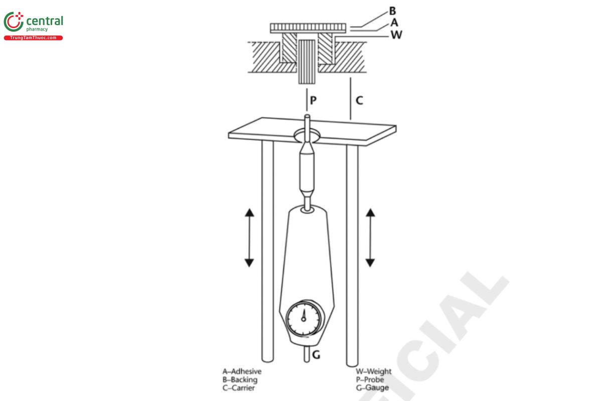
3 APPARATUS
An apparatus can include the following:
- A probe of defined material with inert surface, e.g., stainless steel, and defined surface, e.g., at or minimally convex round with a defined diameter of, e.g., 5.0 mm (i.e., about 20 mm2).
- An annular ring whose dimensions are slightly larger than the probe diameter. The ring should have a low weight, e.g., about 20 g. A rigid metal plate/panel, e.g., stainless steel, brass, aluminum with predrilled holes may be substituted for the annular ring.
Choose combinations of probe surface area and annular ring weight that will result in a low pressure, e.g., about 10 kPa. Example: A 20-g ring (together with a specimen of negligible weight) will apply a pressure of about 10 kPa on a 20-mm2 surface. Alternatively, a rigid plate instrument, with predrilled holes to be covered by the TDS, can be programmed to apply a specified threshold force.
Enabling either the probe or the sample to move, a test system should be capable of bringing the probe into contact with the adhesive surface at a specified approach speed, allowing the probe to adhere to the adhesive surface at a defined force and dwell time, and reversing the direction to detach the probe from the adhesive surface at the specified reverse speed.
The system should be capable of measuring the force when the probe pulls away from the adhesive and recording the maximum force.
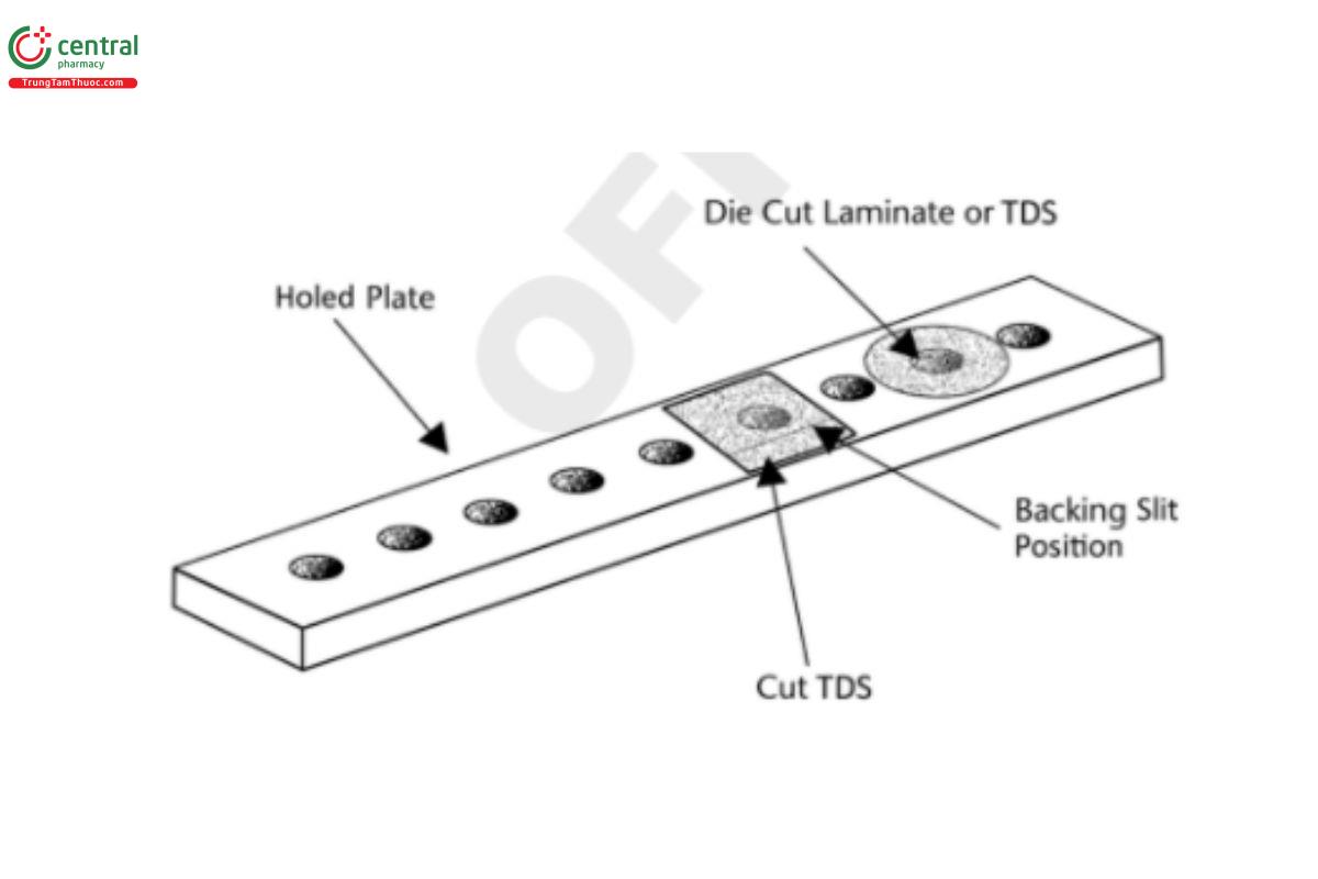
A schematic example of an apparatus used in the probe tack test is shown in Figure 1. Figure 2 illustrates a suitable alternate fixture for mounting the test TDS, a rigid plate with predrilled holes, in place of the annular ring.
4 PROCEDURE
Prior to performing the measurement, the test sample is conditioned at the specified testing conditions (temperature and humidity) for a specified duration.
Check the probe visually for any scratches or damages. Replace if necessary. Clean the probe head with a suitable solvent, removing any potential residue on the surface and without damaging the surface of the probe. Ensure the head is completely dry by allowing the solvent to evaporate or wiping with lint-free wipes.
Cut or punch out an appropriately sized specimen of a TDS, remove the release liner, and place the specimen, sticky side down (avoiding the location of the release liner slit), on the annular ring weight. The specimen must be large enough to cover the entire oriffice and annular ring. Make sure there are no wrinkles on the TDS surface area at the site of the ring’s oriffice. Alternately (when using plates), clean the plate with a suitable solvent, and wipe to dryness with lint-free wipes. Ensure that the contact holes are free from objects or adhesive that would interfere with the probe. Remove the release liner and then place the sticky side of the TDS onto the rigid plate, centered around a predrilled hole (ensuring no wrinkles in the specimen and avoiding the location of the slit release liner (see Figure 2). A roller covered with silicone rubber with predefined weight and with a width enough to cover the TDS width may be used to apply constant force to the TDS to properly adhere onto the plate. Roll the roller without applying vertical force, allowing it to roll freely on the TDS. Turn the plate over so the sticky side of the TDS faces up through the predrilled holes, and place it on a fixture that secures the plate and allows for x and y plane adjustments.
This will ensure that the probe will contact the exposed adhesive without contacting the plate.
Bring the probe and adhesive surface together at a constant speed (e.g., 10 mm/s) allowing the probe with a defined surface area to lift the specimen with the annular ring, thus applying a constant and low force. Alternatively, when using plates, program a constant force that the probe will apply to the specimen upon contact. Allow for a short and constant dwell time, e.g., 1 s. Separate the probe and the adhesive surface at a constant reversing speed, e.g., 10 mm/s. Record tack as the maximum force required to break the bond.
Perform at least n = 5 measurements with specimen from the same batch, taking one specimen per TDS. Check the probe visually in between replicate measurements and clean the probe head if appropriate. Tack is expressed by recording the maximum force to break the bond between the probe and the adhesive surface or the area under the force per time to break that bond. Clean the probe and store in a place protected from scratching.
5 REFERENCES
1. ASTM International. Former ASTM document D2979-16. Standard Test Method for Pressure-Sensitive Tack of Adhesives Using an Inverted Probe Machine (Withdrawn 2019). West Conshohocken, PA: ASTM International; 2016.
2. ASTM International. ASTM D907-15, Standard Terminology of Adhesives. West Conshohocken, PA: ASTM International; 2015.
3. ASTM International. ASTM E6-15e4, Standard Terminology Relating to Methods of Mechanical Testing. West Conshohocken, PA: ASTM International; 2015. (USP 1-Aug-2023)
1 The primary ASTM reference used as the basis for developing a probe tack measurement of topical and transdermal delivery systems (ASTM D2979-16 Standard Test Method for Pressure-Sensitive Tack of Adhesives Using an Inverted Probe Machine) was withdrawn in 2019.
