Measurement of Structural Strength of Semisolids by Penetrometry
If you find any inaccurate information, please let us know by providing your feedback here


This article is compiled based on the United States Pharmacopeia (USP) – 2025 Edition
Issued and maintained by the United States Pharmacopeial Convention (USP)
1 INTRODUCTION
This chapter describes the empirical methods of measuring the structural strength, or consistency, of a semisolid raw material or dosage form with a penetrometer. Viscosity represents the proportionality of the shear stress to the shear rate for a Newtonian uid, whereas consistency is the term for this proportionality for semisolids that exhibit non-Newtonian rheological behavior. Because the term "consistency" may be confused with "uniformity" or "homogeneity", the term "structural strength" is now the preferred term. In the remainder of this chapter we will use the term structural strength to refer to this property of semisolids. One component of the structural strength of a semisolid is its hardness (yield stress). Penetrometry is one method for quantifying the hardness (yield stress) of semisolid materials.
Penetrometry allows a metal cone, with standardized dimensions and weight, to penetrate into a semisolid until the buoyancy of the cone and the yield stress of the semisolid exactly balance the gravity-applied force driving the penetrating object into the semisolid. This observed yield stress of the semisolid is a measure of the semisolid hardness. The yield stress (hardness) of the semisolid will be inversely proportional to the penetration depth of the cone.
This chapter outlines the method for performing the gravity-driven penetrometry measurements of semisolids. Although the results of the penetrometry measurements may be used to calculate the yield stress of the semisolid (see Measurement of Yield Stress (CN 1-Dec-2023) of Semisolids 〈1912〉 for more information), the results of the penetrometry experiment are reported as the observed penetration depth in tenths of millimeters [decimillimeters (dmm)].1,2,3
Change to read:
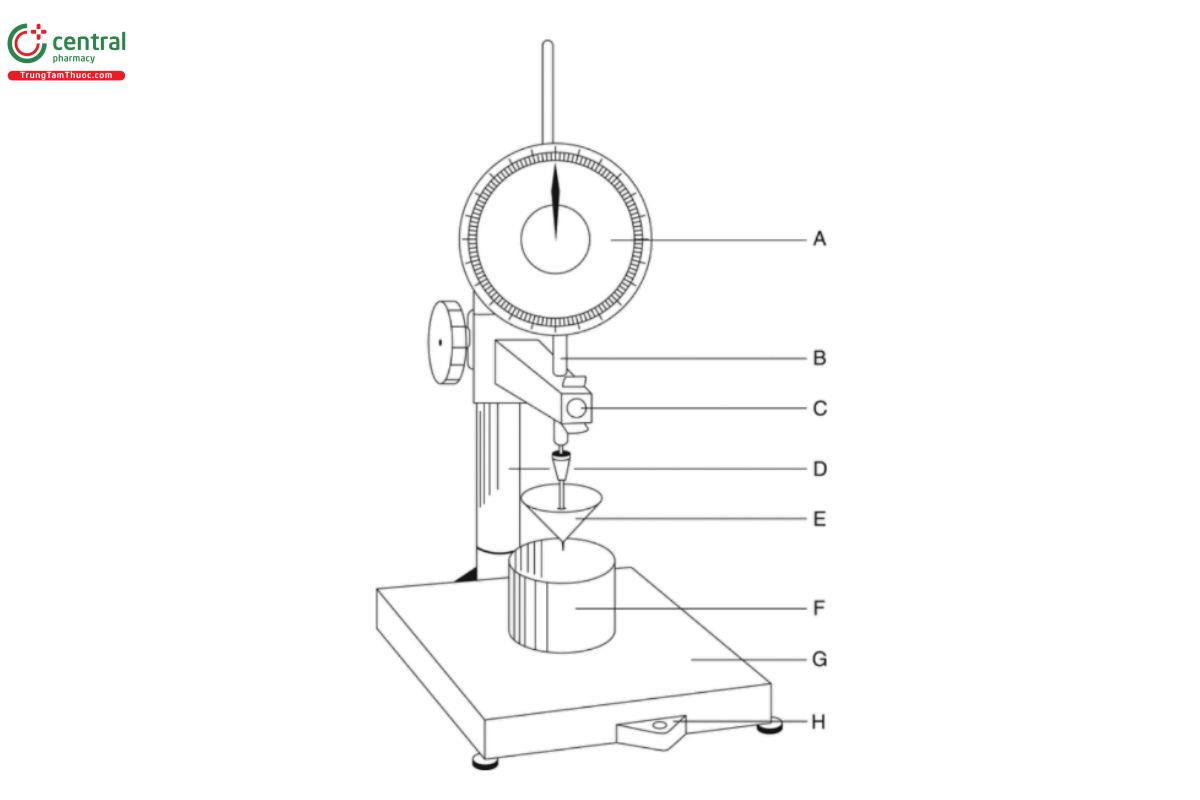
2 APPARATUS
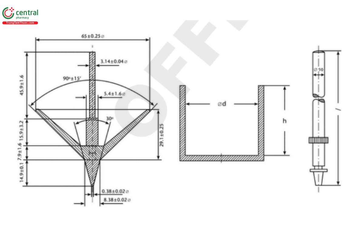
The apparatus consists of a penetrometer made up of a stand and a penetrating object. An example of a suitable stand is shown in Figure 1, and a suitable penetrating object (cone) is shown in Figure 2.
With samples having penetrations ˂200 dmm, three tests (and sometimes more) may be made in one container by proper spacing. To prevent one test from being affected by the disturbed area of a previous test, the tip of the cone must not be placed nearer the edge of a previous test than the penetration distance of the sample. Some harder samples tend to form a marked depression in the center upon solidifying; such samples should not be tested in this depression because the results obtained may be different from those obtained in off center positions on the level surface.
With samples having penetrations ˃200 dmm, only one test may be made in a container by placing the cone tip near the center of the container.
Fill the required number of containers to within 6 mm of their rims.
Prepare the test samples using one of the following procedures:
1. Carefully ll containers without forming air bubbles. Level, if necessary, to obtain a flat surface. Store the samples at 25 ± 0.5° for 24 h, unless otherwise prescribed.
2. Liquefy (i.e., heat to above the melting point) samples, and carefully ll containers without forming air bubbles. Store the samples at 25 ± 0.5° for 24 h, unless otherwise prescribed.
3. If worked (sheared) samples are to be tested, first store samples at 25 ± 0.5° for 24 h. Apply a suitable shear to the samples for 5 min. Carefully and completely ll containers without forming air bubbles, and level, if necessary, to obtain a flat surface.
3 Determination of Penetration
Penetration experiments use a gravity-driven apparatus (as shown in Figure 1 or another functionally equivalent apparatus). Method I uses a standard cone as a penetrating object, and Method II uses a standard needle as a penetrating object. Unless otherwise directed in the individual monograph, use Method I.
method I (gravity-driven measurement of structural strength with standard cone)
1. This method requires the use of a penetrating object that complies with the dimensions of Figure 2. The penetrating object should have a total effective mass of 150.0 ± 0.1 g (including the weight of the cone and additional masses firmly attached during the penetration experiment).
2. Place the test sample on the base of the penetrometer, and verify that its surface is perpendicular to the vertical axis of the penetrating object.
3. Bring the temperature of the penetrating object to 23.5 ± 2.0°, and then adjust its position such that its tip just touches the surface of the sample. [Note—Watching the shadow of the tip is an aid in accurate setting.]
4. Release the penetrating object and allow it to descend, without restraint, for 5 s.
5. Clamp the penetrating object and measure the depth of penetration.
. Repeat the test at least two more times to obtain three or more values.
method II (gravity-driven measurement of structural strength with needle)
1. This method requires the use of a polished metal needle weighing 2.50 ± 0.05 g and having a truncated symmetric tapered angle of 9°0′ ± 15′. The needle is tapered, with a length of 25.4 mm, and the shaft attached to the needle is 58 mm in length and 3.17 mm in diameter. The penetrating object should have a total effective mass of 100.0 ± 0.1 g (including the weight of the needle and additional masses firmly attached during the penetration experiment).
2. Place the test sample on the base of the penetrometer, and verify that its surface is perpendicular to the vertical axis of the penetrating object.
3. Bring the temperature of the penetrating object to 23.5 ± 2.0°, and then adjust its position such that its tip just touches the surface of the sample. [Note—Watching the shadow of the tip is an aid in accurate setting.]
4. Release the penetrating object and allow it to descend, without restraint, for 5 s.
5. Clamp the penetrating object and measure the depth of penetration.
. Repeat the test at least two more times to obtain three or more values.
4 EXPRESSION OF THE RESULTS
Report the mean and standard deviation of at least three replicate measurements in units of penetration depth. The penetration depth is expressed in dmm. If any of the individual results differ from the mean by ˃3%, repeat the test and report the mean and standard deviation of six replicate measurements in units of penetration depth.
5 GLOSSARY
Structural strength (Consistency):
The term "consistency" is sometimes used synonymously with "viscosity", albeit incorrectly. Viscosity represents the proportionality of the shear stress to the shear rate for a Newtonian uid, whereas consistency is the term for this proportionality for semisolids that exhibit non Newtonian rheological behavior. Because the term consistency may be confused with uniformity or homogeneity the term structural strength is now the preferred term. See 〈1912〉 for more information.
Hardness:
"Hardness" is a term used synonymously with "tensile stress", and yield stress is one type of tensile stress. Hardness is proportional to yield stress—a harder semisolid also exhibits a larger apparent yield stress. In penetrometry, hardness has been more specifically defined as H = C × W/pn, where C is a constant dependent on the cone geometry, W is the weight of the penetrating cone, p is the depth of penetration, and n is an exponent. When n = 2, hardness has the same units as yield stress [pascal (Pa)]. See 〈1912〉 for more information.
Penetrometer:
An instrument that measures the structural strength of semisolid materials by measuring the depth to which a specified cone or needle under a given force falls into the material.
1 ASTM D937-97. Standard test method for cone penetration of petrolatum. West Conshohocken, PA: ASTM; 1997.
2 ASTM D217. Standard test methods for cone penetration of lubricating grease. West Conshohocken, PA: ASTM; 1997.
3 European Pharmacopoeia 5.0, 2.9.9. Measurement of consistency by penetrometry. Strasbourg, France: European Directorate for the Quality of Medicine and Healthcare; 2014.
