INHALATION AND NASAL DRUG PRODUCTS: AEROSOLS, SPRAYS, AND POWDERS—PERFORMANCE QUALITY TESTS
If you find any inaccurate information, please let us know by providing your feedback here


Tóm tắt nội dung
- INTRODUCTION
- DELIVERED DOSE UNIFORMITY
- DROPLET/PARTICLE SIZE DISTRIBUTION—NASAL AEROSOLS AND NASAL SPRAYS
- AERODYNAMIC PARTICLE/DROPLET SIZE DISTRIBUTION—INHALATION AEROSOLS, INHALATION SPRAYS, INHALATION POWDERS, NASAL AEROSOLS, AND NASAL POWDERS
- General Principles of Aerodynamic Particle/Droplet Size Distribution Measurement
- Andersen Cascade Impactor without Pre-separator for Inhalation Aerosols, Inhalation Sprays, and Nasal Aerosols
- Andersen Cascade Impactor with Pre-separator for Inhalation Powders and Nasal Powders
- Next Generation Impactor without Pre-separator for Inhalation Aerosols, Inhalation Sprays, and Nasal Aerosols
- Next Generation Impactor with Pre-separator for Inhalation Powders and Nasal Powders
This article is compiled based on the United States Pharmacopeia (USP) – 2025 Edition
Issued and maintained by the United States Pharmacopeial Convention (USP)
1 INTRODUCTION
The major performance measures for inhalation and nasal aerosols, sprays, and powders (each referred to as "test product") relate to dose delivery to the patient, including delivered dose uniformity (DDU) and relevant measures of particle size (optical and/or aerodynamic) depending on the drug product. [Note—The word "dose" should not be confused with the clinical term but is used for quality purposes to refer to the minimum amount required to make the test functional.] Each of these is described in the following sections. A nomenclature table appears in Inhalation and Nasal Drug Products—General Information and Product Quality Tests 〈5〉 from which the descriptive terms for various dosage forms can be obtained. [Note—Typically, the word "spray" is used for spray drug products (e.g., inhalation and nasal spray drug products), and "actuation" is used for inhalation and nasal aerosol and powder drug products. However, actuation(s) and spray(s) are used interchangeably in the methods in this chapter.]
Change to read:
2 DELIVERED DOSE UNIFORMITY
2.1 Inhalation Aerosols and Inhalation Sprays
The following tests are applicable to inhalation aerosols (commonly known as [pressurized] metered-dose inhalers) and inhalation sprays. Inhalation aerosols are formulated as suspensions or solutions of one or more drug substances in propellant(s) and possibly other suitable excipients and are presented as multidose units. Inhalation sprays typically are aqueous-based liquid formulations packaged in a compact container–closure system containing an integral spray pump unit. Refer to 〈5〉 for additional information. The following performance quality test methods are specific to these products and may require modification when alternative inhalation products (for example, breath-actuated inhalation aerosols or inhalation sprays) are tested. However, pharmacopeial requirements for all metered inhalation dosage forms require determination of the DDU and aerodynamic particle size distribution (APSD). In all cases and for all tests, prepare and test the product as directed on the label and the instructions for use. When these directions are not provided by the product manufacturer, follow the precise discharge directions included in the following tests.
Delivered dose uniformity of inhalation aerosols and inhalation sprays
The test for Delivered Dose Uniformity is required for inhalation aerosols and inhalation sprays containing drug formulation either in device-metered or in premetered unit presentations. The test for Delivered Dose Uniformity includes dose uniformity over the entire unit life. (For products packaged in premetered dosage units, see also Uniformity of Dosage Units 〈905〉.) A dose in this test is defined as the minimum recommended number of actuations/sprays specified in the product labeling or instructions for use but not more than 2 actuations/sprays per determination. For inhalation aerosols and inhalation sprays, the drug delivered from the mouthpiece is specified by the label claim. Its value reflects the expected mean drug content for a large number of delivered actuations/sprays collected from many units of the product using the method specified in the monograph. For drug products equipped with an integral spacer, it should be emphasized that the quantity to be measured (label claim) is the drug delivered at the mouthpiece of the spacer, under specified in vitro test conditions.
Unless otherwise directed in the individual monograph, the drug content of the delivered dose collected at the beginning of unit life (after priming as described on the label or instructions for use) and end of unit life of the label claim, will be determined from each of 10 separate containers (i.e., a total of 20 determinations).
A.1.1.1 Sampling the delivered dose from inhalation aerosols and inhalation sprays
DDU sampling apparatus A procedure: To determine the content of drug substance in the discharged plume from an inhalation aerosol and inhalation spray, use DDU sampling apparatus A (see Figure 1a and Table 1).
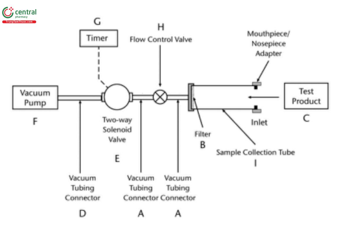
Figure 1a. DDU sampling apparatus for inhalation aerosol, inhalation spray, nasal aerosol, and nasal spray drug products. (See Table 1 for component specifications for DDU sampling apparatus A.) [Note—The volumetric flow rate must be determined and fixed before the test product is inserted in Figure 1a.]
Unless otherwise specified in the individual monograph, with the vacuum pump running, ensure an airflow rate through the device of 28.3 L of air/min (±5%) or 30 L/min (±5%) as applicable for the apparatus selected for APSD determination. Prepare the product for use according to the label instructions for shaking, priming, and ring. Collect the minimum recommended number of actuations following priming. Discharge the first actuation of the minimum recommended actuations into the sampling apparatus through the mouthpiece adapter by actuating the metering system for a duration sufficient to ensure that the dose has been completely discharged. The volume of air sampled per actuation should not exceed 2.0 L (±5%) (e.g., a timer-operated solenoid valve can be used to achieve the required volume). If the minimum recommended dose consists of more than one actuation, wait for 5 s and collect the next actuation. The actuations between the two test samples (i.e., beginning and end of unit life) should be disposed of appropriately. Note that for inhalation aerosols the rate of discharges (number of discharges per unit time) to waste should not cause canister cooling that may affect subsequent test results. This should be evaluated for each drug product. Following each collection of the minimum number of actuations from each unit at each sequential test sample (not more than 2 actuations), detach the test product from DDU sampling apparatus A (see Figure 1a), and disconnect the vacuum pump.
Separately assay the contents of the apparatus for drug for each delivered dose at the beginning and end of sequential test samples after rinsing the filter and the interior of the sample collection tube with a suitable solvent. A validated analytical method is employed to determine the amount of drug in each delivered dose, and data are reported as amount delivered and as a percentage of label claim.
DDU sampling apparatus A: The DDU sampling apparatus is presented in Figure 1a. DDU Sampling apparatus A consists of different accessories (see Figure 1a and Table 1) and a sample collection tube assembly (Figure 2). The latter includes a filter support base with an open mesh filter support such as a stainless-steel screen. The sample collection tube is clamped or screwed to the filter support base, with a mouthpiece adapter to ensure an airtight seal between the sample collection tube and the mouthpiece. Use a mouthpiece adapter that ensures that the opening of the product's mouthpiece is flush with the front face or 2.5-mm indented shoulder in the sample collection tube to make an airtight seal. The sample collection tube is connected to a system comprising a vacuum pump and flow-control valve (see Figure 1a).
The vacuum pump should be capable of pulling air through the complete assembly, including the filter and the test product to be tested, at the desired flow rate. Connect the flowmeter to set the flow rate for DDU analysis (e.g., 28.3 L/min (±5%) or 30 L/min (±5%) as applicable). Replace the flowmeter with the test product for DDU determination. The flow rate should be in accordance with the test requirements of the drug product being evaluated.
During tests of inhalation aerosols and sprays, air should be drawn continuously through the system to avoid loss of drug into the atmosphere. The filter support base is designed to accommodate 25-mm diameter filter disks (see Figure 2). At the flow rate used, the sample collection tube and the filter must be capable of quantitatively collecting the delivered dose. The filter and other materials used in the construction of the apparatus must be compatible with the drug and the solvents that are used to extract the drug from the filter. One end of the sample collection tube is designed to hold the filter tightly against the filter support base using an O-ring as needed. When assembled, the joints between the components of the apparatus are airtight so that when a vacuum is applied to the base of the filter, all of the air drawn through the DDU sampling apparatus passes through the device component. The description for Figure 1b appears in A.3.1.1. Sampling the delivered dose from inhalation powders.
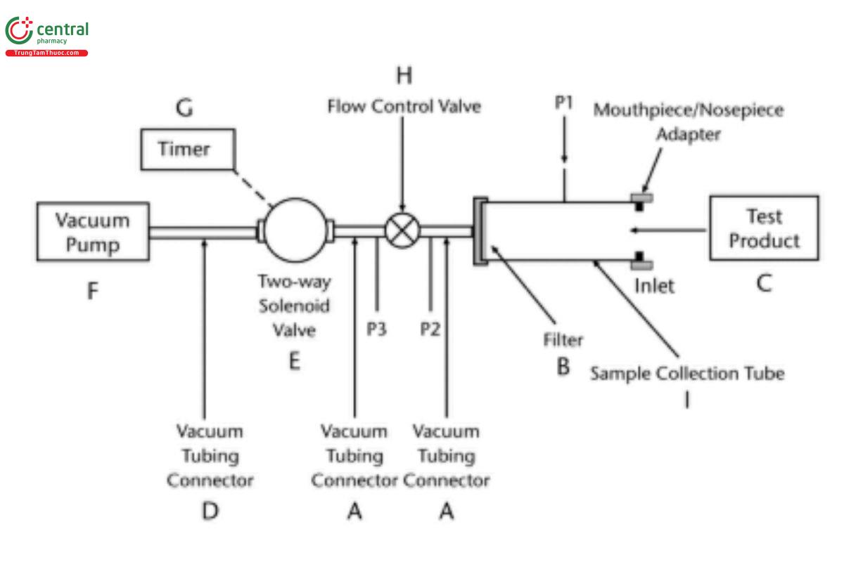
Figure 1b. DDU sampling apparatus for inhalation powder and nasal powder drug products. (See Table 1 for component specifications for DDU sampling apparatuses A and B.) [Note—The volumetric flow rate must be determined and fixed before the test product is inserted.]
Table 1. Component specifications for Figure 1a and Figure 1b
Code | Item | Descriptions | |
DDU Sampling Apparatus A [Figure 1a] (inhalation aerosols, inhalation sprays, nasal aerosols, and nasal sprays) | DDU Sampling Apparatus B [Figure 1b] (inhalation powders and nasal powders) | ||
A | Vacuum tubing connector | A short length of suitable vacuum tubing, e.g., silicone tubing with 10.0-mm IDa and 16.0-mm ODb | A short length of suitable vacuum tubing, e.g., silicone tubing with 10.0-mm ID, 16.0- mm OD, and a connector to pressure tap P2 |
B | filter | 25-mm glass fiber filter, stainless steel fiber filter, or microber polypropylene filter | 47-mm glass fiber filter, stainless steel fiber filter, or microber polypropylene filter |
C | Flowmeter or test product | Inhalation or nasal aerosol or spray products to be evaluated | Inhalation or nasal powder products to be evaluated |
D | Vacuum tubing connector | A short length of suitable vacuum tubing, e.g., silicone tubing with 16.0-mm ID | A short length of suitable vacuum tubing, e.g., silicone tubing with 16.0-mm ID and with or without a connector to pressure tap P3 |
E | Two-way solenoid valve | Two-way, two-port solenoid valve with an opening response time of ≤100 ms | |
F | Vacuum pump | Vacuum pump capable of drawing air through the complete assembly, including the filter, mouthpiece/nosepiece adaptor, and test product, at the required flow rate | Vacuum pump capable of drawing air through the complete assembly, including the filter, mouthpiece/nosepiece adaptor, and test product, at the required flow rate under critical (sonic) conditions (P3/P2 < 0.5) |
G | Timer | Timer that switches current directly to the solenoid valve for the required duration | |
H | Flow control valve | Adjustable regulating valve with flow coefficient (CV)c ≥1 V | |
I | Sample collection tube | 26.70-mm ID × 9.4-cm ILd | 34.85-mm ID × 12.0 -cm IL |
P1 | Pressure tap | Not applicable | 2.2-mm ID, 3.1-mm OD; flush with the internal surface of the sample collection tube, centered and burr-free, 59-mm from its inlet. Pressure measurements determined under steady-state flow conditions with a differential pressure transducer. The pressure tap must not be open to the atmosphere during dose collection. |
P2, P3 | Pressure tap | Not applicable | Pressure measurements determined under steady-state flow conditions with an absolute pressure transducer. The pressure taps must not be open to the atmosphere during dose collection. |
aID: inside diameter
b OD: outside diameter
c Flow coefficient (CV), as defined by ISA S75.02 Control valve capacity test procedures in Standards and Recommended Practices for Instrumentation and Control, 10th ed., Vol. 2. Research Triangle Park, NC: Instrument Society of America; 1989.
dIL: inside length
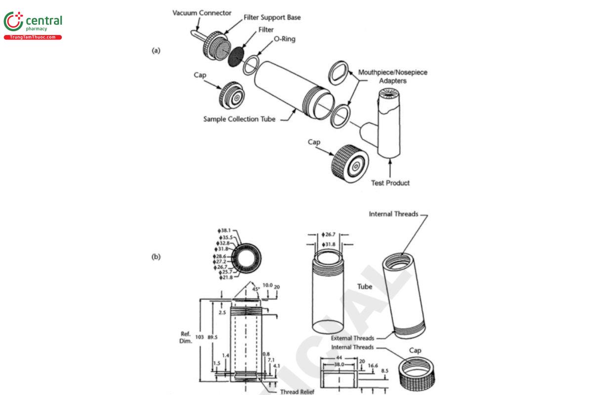
Figure 2. DDU sample collection tube (Table 1) assembly for inhalation and nasal aerosol, nasal spray, and nasal powder drug products. Dimensions are in millimeters unless otherwise stated. For (a) tube assembly components and (b) dimensions of the components of Apparatus A, see Table 1. [Note—The caps as shown in Figure 2 are used to seal the tube during the content evaluation. The gure is a visualization of the table, not an engineering drawing.]
[Note—The screw thread rinsing cap shown in Figure 2 may be replaced by cap utilizing a bayonet fitting without changing any other aspect of the apparatus.]
2.2 Nasal Aerosols and Nasal Sprays
The following test is applicable to nasal aerosols and sprays formulated, respectively, as nonaqueous and aqueous suspensions or solutions of drug, presented typically in multidose containers, and fitted with dose-metering valves or pumps. In all cases and for all tests, prepare and test the spray as directed in the labeling and the instructions for use.
Delivered dose uniformity of nasal aerosols and nasal sprays
Unless otherwise directed in the individual monograph, the drug content of the delivered dose collected at the beginning of unit life (after priming as described on the label or instructions for use) and end of unit life of the label claim, will be determined from each of 10 separate containers (i.e., a total of 20 determinations). This represents a total of 20 determinations. Sampling and measurements shall be made after priming as described in the labeling or instructions for use. A dose in this test is defined as the minimum recommended number of actuations/sprays specified in the product labeling or instructions for use but not more than 2 actuations per determination. Also, for single-use products, Delivered Dose Uniformity of 10 dosage units should be determined separately.
A.2.1.1 Sampling the delivered dose from nasal aerosols: See A.1.1.1 Sampling the delivered dose from inhalation aerosols and inhalation sprays.
A.2.1.2 Sampling the delivered dose from nasal sprays
Procedure: To determine the content of drug substance in the discharged plume from a nasal spray, use DDU sampling apparatus A (see Figure 1a and Table 1) described above. The use of a mechanical means of actuating the metering system or pump assembly to deliver doses for collection is recommended to ensure reproducible in vitro dose collection. The mechanical actuation procedure should have adequate controls for the critical mechanical actuation parameters (e.g., actuation force, actuation speed, stroke length, and rest periods). The test must be performed on units that have been thoroughly shaken and primed according to the instructions for patient use. The test unit should be actuated in a vertical or near-vertical, pump up position. The sprays at the beginning of each of the 10 test containers should be the sprays immediately following priming and the sprays at the end (label claim) of each from the same container. This represents a total of 20 determinations. The doses between the beginning and end sequential test samples must be disposed of appropriately. A validated analytical method is employed to determine the amount of drug in each delivered dose, and data are reported as amount delivered and as a percentage of label claim.
2.3 Inhalation Powders
The following tests are applicable to inhalation powders (commonly known as dry powder inhalers [DPIs]) presented as premetered or device-metered units. Pharmacopeial requirements for all of these drug products require determination of each of the delivered doses and APSD. In all cases and for all tests, prepare and test the product as directed in the labeling and the instructions for use. When these directions are not provided by the product manufacturer, follow the precise dose-discharge directions included in the following tests.
A.3.1 Delivered dose uniformity of inhalation powders
Perform this test under conditions of controlled temperature and humidity.
The test for Delivered Dose Uniformity is required for inhalation powders in premetered (including ordered multiple dose) and device metered presentations as labeled for use with the specified delivery system. The test for Delivered Dose Uniformity over the entire unit life is required for drug products packaged in device-metered or in ordered multiple-dose metering units of nominal premetered dosage units that have a predetermined dose sequence. For formulations packaged in premetered dosage units, an additional test, Uniformity of Dosage Units 〈905〉 is also required. Note that the target-delivered dose is determined by the mean drug content for a large number of delivered doses collected from many units under defined experimental conditions as specified in the product labeling. In many cases, the target value may depend on the manner in which the test for Delivered Dose Uniformity is performed. For inhalation powders, where the label claim usually is the nominal premetered or device-metered dose of drug, the target-delivered dose and the method are specified in the individual monograph, and usually the target-delivered dose is less than the label claim.
Unless otherwise directed in the individual monograph, the drug content of the delivered dose from each of 10 separate units is determined separately.
The drug content of the delivered dose from each unit will be collected at the beginning and end of unit life per the label claim. Thus, two determinations will be obtained from each of 10 separate drug product units. This represents a total of 20 determinations. For single-use products and for inhalation powders packaged in premetered single dosage form units, Delivered Dose Uniformity of 10 dosage units should be determined separately.
A.3.1.1 Sampling the delivered dose from inhalation powders: DDU sampling apparatus B should be used to determine the content of drug substance emitted from the mouthpiece of an inhalation powder (see Figure 1b and Table 1). This apparatus is capable of sampling the emitted dose at a variety of flow rates.
DDU sampling apparatus B procedure: Adjust the flow-control valve to provide the flow that has been determined to induce a 4-kPa pressure drop across the test product to be tested and for a period of T seconds consistent with the withdrawal of 2.0 L (±5%) of air from the mouthpiece of the test product. [Note—If the flow rate and duration are defined otherwise in the monograph, adjust the system to within 5% of those values.] The volume of air sampled should not exceed 2.0 L (±5%) . This flow rate should be fixed for all determinations for a specific drug product, established and validated during development studies as the suitable flow rate through the device to produce such pressure drop on the average. The flow rate should not be changed to compensate for device-to-device variability in flow resistance for the same product.
Determine the test flow rate using DDU sampling apparatus B as follows. Insert the product into the mouthpiece adapter to ensure an airtight seal. For premetered products, use a device loaded with an empty capsule or blister. For device-metered products, use an unused device. In both cases, the flow path should be free of drug. Connect one port of a differential pressure transducer to the pressure tap, P1 (in Figure 1b), and leave the other open to the atmosphere. Switch on the pump, and open the two-way solenoid valve. Adjust the flow control valve until the pressure drop across the product is 4.0 kPa. Ensure that critical (sonic) flow occurs in the flow-control valve by measuring the individual values for absolute pressure, P2 and P3, so that their ratio P3/P2 is ≤0.5. If this ratio of P3/P2 is not achieved, switch to a more powerful pump and remeasure the test flow rate. Critical (sonic) flow conditions in the flow-control valve are required in order to ensure that the volumetric flow rate drawn from the mouthpiece is unaffected by pump fluctuations and changes in flow resistance of the test product. Remove the test product and the mouthpiece adapter, and without disturbing the flow-control valve, measure the flow rate drawn from the mouthpiece, Qout . A flowmeter is connected in an airtight fashion at out the inlet to the sampling apparatus (see Figure 1b) using a suitable adapter. Use a flowmeter calibrated for the volumetric flow leaving the meter in an airtight fashion to directly determine Qout . If the flow rate is >100 L of air/min, adjust the flow-control valve until Q equals 100 L/min; otherwise, record the value of Qout, and leave the flow-control valve undisturbed. define the test flow duration in seconds, e.g., at 60L/min, T = 120/Qout, so that a volume of 2.0 L (±5%) of air is withdrawn from the product at the test flow rate Qout, and adjust the timer out controlling the operation of the two-way solenoid valve accordingly.
Prepare the device with powder for inhalation according to the labeled instructions. With the vacuum pump running and the solenoid valve closed, insert the test product's mouthpiece horizontally into the mouthpiece adapter. Discharge the powder into DDU sampling apparatus B by activating the timer controlling the solenoid valve and withdrawing 2.0 L (±5%) of air from the product at the previously defined flow rate. Repeat the whole operation n − 1 times beginning with the text, "Prepare the device with powder", where n is the number of actuations defined in the labeling as the minimum recommended dose, but not more than 2 actuations per determination. Detach the inhalation powder device container from DDU sampling apparatus B, and disconnect the vacuum tubing connector, D (Figure 1b). Assay the contents of the apparatus for drug after rinsing the filter and the interior of the sample collection tube with a suitable solvent.
DDU sampling apparatus B: The sample collection tube assembly is similar to that described in Figure 2 for testing inhalation aerosols. In this case, however, the filter and sample collection tube have a larger internal diameter to accommodate a 47-mm diameter filter (Table 1). This feature enables dosage collection at higher flow rates—up to 100 L of air/min—when necessary. A mouthpiece adapter ensures an airtight seal between the sample collection tube and the mouthpiece of the inhalation powder being tested. The mouthpiece adapter must ensure that the tip of the product's mouthpiece is flush with the open end of the sample collection tube. Tubing connectors, if they are used, should have an internal diameter of ≥10 mm to preclude their own internal diameters from creating significant flow resistance. A vacuum pump with excess capacity must be selected in order to draw air at the designated volumetric flow rate through both the sampling apparatus and the test product simultaneously. A timer-controlled, low-resistance, solenoid-operated, two-way valve is interposed between the vacuum pump and the flow-control valve to control the duration of flow. Flow control is achieved by ensuring that critical (sonic) flow occurs in the flow-control valve (absolute pressure ratio P3/P2 is ≤0.5 under conditions of steady-state flow). A validated analytical method is employed to determine the amount of drug in each delivered dose, and data are reported as amount delivered and as a percentage of target-delivered label claim.
2.4 Nasal Powders
The following test is applicable to nasal powders presented in premetered and device-metered units. In all cases and for all tests, prepare and test the powder as directed in the labeling and the instructions for use, but not more than 2 actuations per determination.
A.4.1 Delivered dose uniformity of nasal powders
Unless otherwise directed in the individual monograph, the drug content of the minimum number of delivered dose(s) will be determined at the beginning of unit life and also at the end of unit life from each of 10 separate containers. This represents a total of 20 determinations. For nasal powders packaged in single-dose units, Delivered Dose Uniformity can be applied on 10 dosage units.
A.4.1.1 Sampling the delivered dose from nasal powders: To ensure reproducible dose collection, it is recommended that appropriate means of operating the device assembly be used to deliver doses for collection. (See A.3.1 Delivered Dose Uniformity of Inhalation Powders, A.3.1.1 Sampling the delivered dose from inhalation powders for additional information regarding the sampling procedure.) The two separate determinations (not more than 2 actuations) include samples of the beginning and end of the unit life corresponding to the label claim from each of 10 units. The discharges between the two sequential beginning and end test samples for each unit must be disposed of appropriately. A validated analytical method is used to determine the amount of drug in each delivered dose. Data are reported as amount delivered and as a percentage of target-delivered label claim. DDU sampling apparatus B (Figure 1b and Figure 2) is recommended for nasal powders.
Change to read:
3 DROPLET/PARTICLE SIZE DISTRIBUTION—NASAL AEROSOLS AND NASAL SPRAYS
For suspension or solution nasal aerosols and nasal sprays, the emitted droplet/particle size distribution should be determined for the delivered plume subsequent to delivery under specified experimental conditions. Assuming that the density of the liquid under investigation is constant irrespective of droplet size, the volume-based size distributions may be treated as mass-based size distributions for the purpose of data interpretation. If a laser diffraction method is used (for more detail, refer to the description of this method in B.1 Droplet/Particle Size Determination by Laser Diffraction), droplet size distribution can be estimated in terms of ranges for the 10th (D10), 50th (D50 ), and 90th (D90) percentiles of the cumulative volume-based size distribution, as well as the span of the distribution, expressed as [(D90− D10)/D50], and the percentage of droplets less than 10 µm. Note that D is identical with the volume median diameter if the distribution is unimodal.
Appropriate and validated or calibrated emitted droplet/particle size analytical procedures should be described in sufficient detail to allow accurate and reproducible assessment including the following:
Complete information about the apparatus and accessories
Theoretical model (Lorenz–Mie or Fraunhofer approximation)
The application of a disabling option for one or more of the innermost detectors to mitigate beam steering effects (only applicable to nasal aerosols)
Software version
Sample placement with respect to the optical bench of the laser diffractometer
Measurement range
Beam width
Laser trigger condition in connection with the initiation and termination of the measurement sequence
Lower limit of detection (if laser triggering is not used)
Obscuration limit (upper bound of detection range in terms of particle concentration)
3.1 Droplet/Particle Size Determination by Laser Diffraction
Suspension and solution drug products intended for application to the nasal cavity produce liquid droplets that typically are much larger than the operating range for multistage inertial impactors. Thus, laser diffraction (sometimes referred to as low-angle laser light scattering) could be a complementary and/or an alternative approach for determining the size distribution.
The theory and operating principles for laser diffraction are well described in the most recent version of ISO 13320. These systems use the light-scattering pattern produced by passage of a cloud of droplets through the measurement zone to develop the volume-based size distribution in an iterative process in which a theoretical model (either Fraunhofer or Lorenz–Mie) is used to interpret the data. The process is summarized schematically in Figure 3. [Note—If the Lorenz–Mie model option is chosen, it will be necessary to input values for the real (refraction) and imaginary (absorption) components of refractive index for the liquid being studied. Manufacturers of laser diffraction equipment provide this information for commonly encountered liquid media either on their website or upon inquiry.]
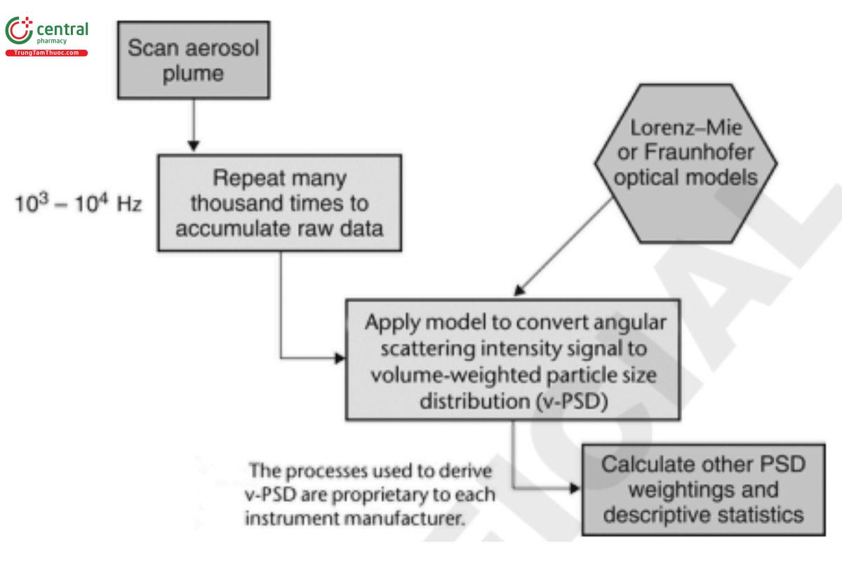
Figure 3. Conversion of light-scattering data into a droplet/particle size distribution by laser diffractometry. (PSD is particle size distribution.)
An apparatus that has the capability to assess aerosols or sprays is required. [Note—Not all commercially available laser diffractions possess this capability.] Set up the measurement system in accordance with the procedure outlined schematically in Figure 4.
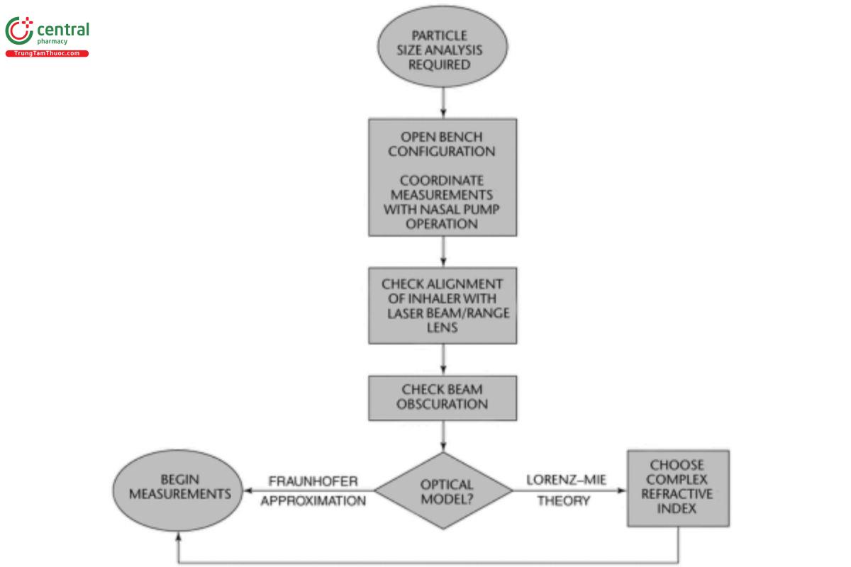
Figure 4. Setup for laser diffractometry with a nasal drug product.
Nasal spray drug products generally are determined with an open-bench arrangement with an automated actuation station setup so that reproducibility in nasal product operation from one actuation to the next can be optimized. Check the alignment of the test product plume intersecting with the optical configuration of the laser diffractometer using the tools provided by the manufacturer to optimize alignment of the optical bench. Check that the light beam obscuration is within the upper and lower limits specified by the manufacturer, consulting the operator's manual for the laser diffraction system being used. Vacuum extraction is required to efficiently remove droplets after they pass through the laser. An unrepresentative result may occur if this value is set too low (typically <5%). Unquantiable error due to multiple scattering will happen if the obscuration is above the recommended upper limit. [Note—This limit varies from one manufacturer to another and may also vary from one laser diffractometer system to another from the same manufacturer.]
Conduct as many replicate measurements as needed to achieve a representative data set. Inspect each size distribution presented, ideally in differential volume-based format or equivalent to assess whether or not it is unimodal and symmetrical. A unimodal distribution is a requirement for data analysis.
3.2 Aerodynamic Particle Size Distribution—Determination by Cascade Impaction
The particle or droplet size distribution in the plume discharged from nasal aerosols may be determined similar to inhalation aerosols as described in C. Aerodynamic Particle/Droplet Size Distribution—Inhalation Aerosols, Inhalation Sprays, Inhalation Powders, Nasal Aerosols, and Nasal Powders.
Change to read:
4 AERODYNAMIC PARTICLE/DROPLET SIZE DISTRIBUTION—INHALATION AEROSOLS, INHALATION SPRAYS, INHALATION POWDERS, NASAL AEROSOLS, AND NASAL POWDERS
4.1 General Principles of Aerodynamic Particle/Droplet Size Distribution Measurement
The particle or droplet size distribution in the plume discharged from inhalation aerosols, inhalation sprays, nasal aerosols, and the particle size distribution in the cloud discharged from inhalation powders and nasal powders are important characteristics used in judging product quality and performance. The aerodynamic diameter of an aerosol particle is equal to the diameter of a sphere of unit density whose gravimetric settling velocity is the same. The aerodynamic size distribution defines the manner in which aerosol droplets/particles deposit during inhalation. In use, many test products discharge drug in the form of large droplets or particles (the "ballistic fraction") that leave the inhaler at high velocity and impact on and are captured by the moist surfaces in the mouth, throat, or nose. The remainder of the discharge from the inhaler is the "nonballistic fraction" that is inhaled into the remainder of the respiratory tract.
Cascade impaction devices classify aerosol particles and droplets on the basis of aerodynamic diameters. The principle of their operation whereby they separate aerosol particles and droplets from a moving airstream on the basis of particle or droplet inertia is shown in Figure 5. The internal geometry, surface smoothness, and dimensions of the induction port (and pre-separator if used) may affect the mass of the drug that enters the cascade impactor. These dimensions are carefully defined and are held constant for all apparatuses (see C.1.1 Stage Mensuration). The arithmetic mean surface roughness (Ra ) of the inlet should be around 0.40 μm.
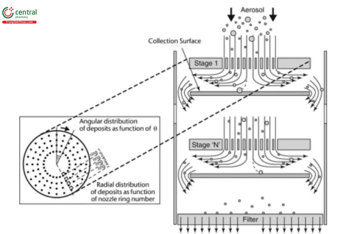
Figure 5. Schematic representation of the principle of operation of cascade impactors.1
C.1.1 Stage mensuration
Calibration of a cascade impactor is a property of the nozzle dimensions, the spatial arrangement of the nozzles and its collection surface, and the flow rate passing through it. Because nozzles can corrode and wear over time, the effective diameter of the nozzles of each stage, which are related to the impaction stage's cut-off size, must be measured precisely on a regular basis. This process, known as stage mensuration, replaces the need for repetitive calibration using standard aerosols and ensures that only impactors that conform to the manufacturer's specifications for the stage nozzles are used for testing product output.
C.1.2 Interstage drug losses (wall losses)
The selected APSD determination procedure should ensure that not more than 5% of the product's total delivered drug mass (into the impactor) is subject to wall loss between the impaction apparatus's collection surfaces. In the event that interstage drug losses are predetermined to be >5% for a given drug product, either the procedure should be modified (e.g., coating of impactor plates should be explored) in such a way that wall losses are decreased below this level or an alternative apparatus should be used. Wall losses on a particular stage should not be combined with the plate deposition to assay the mass deposited on a specific stage. It is appropriate to include wall deposition in the determination of the mass balance.
C.1.3 Re-entrainment
Where method variations are possible, the selected method should seek to minimize particle re-entrainment (from an upper to a lower impaction stage) on stages that contribute to size fractions defined in the individual monograph, especially where this may affect the amounts of drug collected. Minimizing the number of actuations, using coated particle-collection surfaces, and proving that multiple actuation procedures produce results that are statistically similar to those from smaller numbers of actuations are all methods that can be used for this purpose. The number of actuations collected, the time interval between actuations, and the total duration of flow through the cascade impactor should be standardized for the measurement program by appropriately validated approaches.
By using validated analytical methods and a suitable mensurated impaction device, analysts can determine aerodynamic particle size distributions for drugs leaving the mouthpiece/nosepiece of inhalation aerosols, inhalation sprays, inhalation powders, nasal aerosols, or nasal powders. If temperature or humidity limits for use of the product are stated on the label, it may be necessary to control the temperature and humidity of the air surrounding and passing through the device to conform to those limits. Ambient conditions are presumed unless otherwise specified in individual monographs. However, it may be necessary to control the temperature and humidity of the air surrounding and passing through the device.
C.1.4 mass balance
In addition to the size distribution, good analytical practice dictates that a mass balance be performed in order to confirm that the amount of the drug discharged from the product and recovered from the mouthpiece/nosepiece adapter, the induction port through to the after-filter of the cascade impactor apparatus, is within an acceptable range around the target-delivered label claim. The result for the recovered mass can be expressed on a per-actuation basis as a percent of the labeled delivered dose, which represents the dose delivered from the mouthpiece/nosepiece.
The total mass of drug collected in all of the components (mass balance) divided by the total number of actuations discharged per determination typically is not less than 85% and not more than 115% of the target-delivered label claim. This is not a test of the product but serves to ensure that the test results are valid.
C.1.5 procedure
Use one of the following multistage impaction apparatuses to determine aerodynamic particle size distributions of drug(s) leaving the mouthpiece/nosepiece of inhalation aerosols, inhalation sprays, inhalation powders, nasal aerosols, or nasal powders. A justified minimum number of drug product units (e.g., 5) should be tested individually, and the determination for each unit should be performed with the minimum number of actuations justified by the sensitivity of the analytical procedure used to quantitate the deposited drug. The Andersen Cascade Impactor and the Next Generation Impactor without pre-separator are intended for use with inhalation aerosols, inhalation sprays, and nasal aerosols at a single flow rate. The Andersen Cascade Impactor and Next Generation Impactor with pre-separator are intended for use with inhalation powders and nasal powders, unless it has been shown to be unnecessary, at the appropriate flow rate, Q , determined earlier during testing for Delivered Dose Uniformity, see C.3.1 Design—Andersen Cascade Impactor with out
Pre-Separator and C.5.1 Design—Next Generation Impactor with Pre-Separator. The volume of total air sampled per actuation should be 4.0 L. Table 2 indicates the apparatuses used to determine aerodynamic particle size and the products that they are used to evaluate. Table 3a and Table 3b provide the cut-off diameters of the impactors listed in Table 2 at specified flow rates.
Table 2. Aerodynamic Particle Size Apparatuses: Description and the Products That They Can Be Used to Evaluate
Description | Product |
Andersen Cascade Impactor without pre-separator | Inhalation aerosols, inhalation sprays, and nasal aerosols |
Andersen Cascade Impactor with pre-separator | Inhalation powders and nasal powders |
Next Generation Impactor without pre-separator | Inhalation aerosols, inhalation sprays, and nasal aerosols |
Next Generation Impactor with pre-separator | Inhalation powders and nasal powders |
Table 3a. Cut-Off Diameters (µm) for Andersen Cascade Impactor with and without Pre-Separator at 28.3 L/min Compared with Use at 60 and 90 L/min
Stage | 28.3 L/min | 60 L/min | 90 L/min |
−2 | — | — | 8.0 |
−1 | — | 8.6 | 6.5 |
0a | 9.0 | 6.5 | 5.2 |
1 | 5.8 | 4.4 | 3.5 |
2 | 4.7 | 3.2 | 2.6 |
3 | 3.3 | 1.9 | 1.7 |
4 | 2.1 | 1.2 | 1.0 |
5 | 1.1 | 0.55 | 0.22 |
6 | 0.7 | 0.26 | — |
7 | 0.4 | — | — |
a The version of Stage 0 used at 60 and 90 L/min (i.e., −0) has external modifications, permitting another stage rather than the inlet adapter cone to be fitted above it. Its internal characteristics and performance are unaltered.
Table 3b. Cut-off diameters (µm) for Next Generation Impactor with and without Pre-separator at 30, 60, and 100 L/min
Stage | Flow Rate (30 L/min) | Flow Rate (60 L/min) | Flow Rate (100 L/min) |
1 | 11.72 | 8.06 | 6.12 |
2 | 6.40 | 4.46 | 3.42 |
3 | 3.99 | 2.82 | 2.18 |
4 | 2.30 | 1.66 | 1.31 |
5 | 1.36 | 0.94 | 0.72 |
6 | 0.83 | 0.55 | 0.40 |
7 | 0.54 | 0.34 | 0.24 |
MOCa | 0.36 | 0.14 | 0.07 |
a MOC, micro-orifice collector. Sizes correspond to 80% collection efficiency for this back-up stage.
4.2 Andersen Cascade Impactor without Pre-separator for Inhalation Aerosols, Inhalation Sprays, and Nasal Aerosols
Use the Andersen Cascade Impactor without pre-separator at a flow rate of 28.3 L/min (±5%) as specified by the manufacturer of the cascade impactor.
C.2.1 Design—andersen cascade impactor without pre-separator
The design and assembly of this apparatus are shown in Figure 6a. The expanded view of the induction port and entrance cone to
connect the impactor through the induction port to a drug product are shown, respectively, in Figure 6b and Figure 6c. The device is a cascade impactor with eight stages and an after-filter. The material can be aluminum or stainless steel. Use this apparatus at a flow rate of 28.3 L/min (±5%) unless otherwise prescribed in the individual monograph.
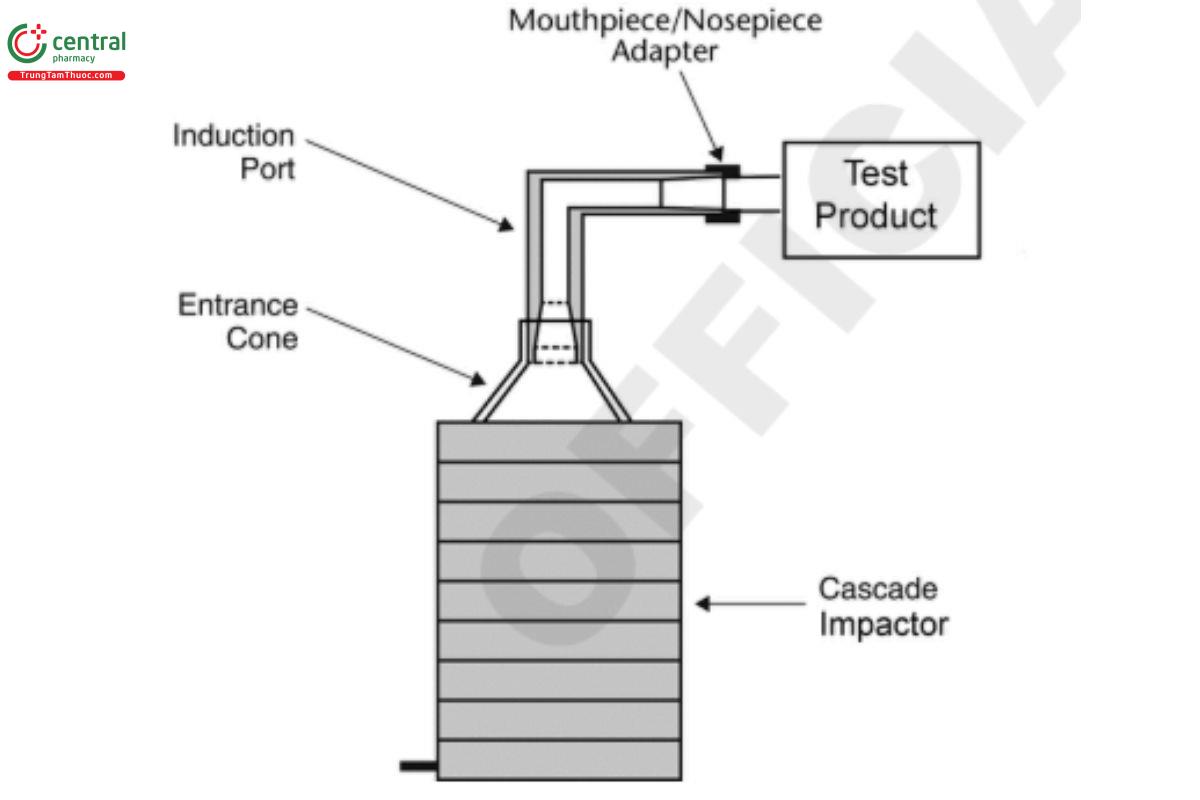
Figure 6a. Andersen Cascade Impactor without pre-separator: Assembly of induction port and entrance cone mounted onto cascade impactor.
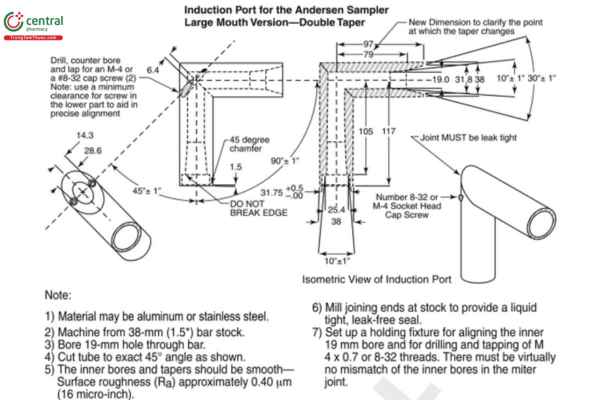
Figure 6b. Expanded view of induction port for use with cascade impactors.
[Note—All inhalation aerosol and powder drug products should employ the USP induction port (see Figure 6b). specific monographs exist with a non-USP induction port because the product was developed before the USP induction port was available and subsequently approved by the FDA.][Note—The external dimensions of the Next Generation Impactor version of the induction port are different than shown.]
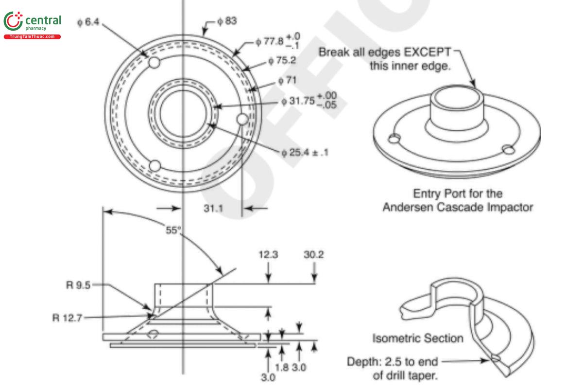
Figure 6c. Expanded view of the entrance cone for mounting induction port on the Andersen Cascade Impactor without pre-separator. Material can be aluminum or stainless steel. Surface roughness (Ra ) should be approximately 0.40 µm.
Manufacturers' critical engineering dimensions for the stages of the Andersen Cascade Impactor are provided in Table 4. During use, some occlusion and blockage of nozzles may occur, and therefore, in-use mensuration tolerances must be justified.
Table 4. Critical Dimensions for the Nozzles of the Andersen Cascade Impactor
Stage Number | Number of Nozzles | Nominal Nozzle Diameter (mm)a |
0 | 96 | 2.550 ± 0.025 |
1 | 96 | 1.890 ± 0.025 |
2 | 400 | 0.914 ± 0.013 |
3 | 400 | 0.711 ± 0.013 |
4 | 400 | 0.533 ± 0.013 |
5 | 400 | 0.343 ± 0.013 |
6 | 400 | 0.254 ± 0.013 |
7 | 201 | 0.254 ± 0.013 |
aRefer to manufacturer for specifications on tolerance/precision of the dimensions.
C.2.2 procedure—andersen cascade impactor without pre-separator
Set up the multistage cascade impactor as described in the manufacturer's literature with an after-filter below the final stage to capture any fine particles that otherwise would escape from the impactor. To ensure efficient particle capture, coat the particle collection surface of each stage appropriately with Glycerol, silicone oil, or other suitable liquid unless this has been demonstrated to be unnecessary. Attach the mouthpiece/nosepiece adapter to the end of the induction port to produce an airtight seal between the product mouthpiece/nosepiece and the induction port as shown in Figure 6a. Use a mouthpiece/nosepiece adapter that ensures that the tip of the product's mouthpiece/nosepiece is flush with the open end of the induction port. Ensure that the various stages of the cascade impactor are connected with airtight seals to prevent leaks (seals should be periodically inspected for cracks and replaced as necessary). Turn on the vacuum pump to draw air through the cascade impactor, and calibrate the flow rate through the system with an appropriate flowmeter attached to the open end of the induction port.
Adjust the flow-control valve on the vacuum pump to achieve steady flow through the system at 28.3 L/min (±1.4 L/min). Prepare the product for use according to the label instructions for shaking, priming, and ring. With the vacuum pump running, insert the mouthpiece/nosepiece of the test product into the mouthpiece/nosepiece adapter and immediately fire into the cascade impactor the first of the minimum recommended number of actuations. When testing, keep the valve depressed for a duration sufficient to ensure that the actuation has been completely discharged. If additional sprays are required for the sample, wait for 5 s before ring the next actuation. Repeat until the required number of actuations has been discharged. The number of minimum recommended actuations discharged per determination must be sufficient to ensure an accurate and precise determination of the APSD, but not excessive to mask the variability of individual doses. After the last actuation has been discharged, remove the product from the mouthpiece/nosepiece adapter. Rinse the mouthpiece/nosepiece adapter and the induction port with a suitable solvent, and dilute quantitatively to an appropriate volume. Disassemble the cascade impactor, place each collection plate or filter in a separate container, and rinse the drug from each of them. [Note—Analyze all components separately. Only data from analysis of deposition on the collection plates should be used for the purpose of determination of stage deposition. The data from analysis of deposition on the other components should only be used for the purpose of establishing the determination of mass balance and should not be combined with the plate deposition for determination of aerodynamic particle size distribution.] Dilute each sample quantitatively to an appropriate volume. Using an appropriately validated method of analysis, determine the mass of drug collected in each of the components.
4.3 Andersen Cascade Impactor with Pre-separator for Inhalation Powders and Nasal Powders
C.3.1 design—andersen cascade impactor with pre-separator
The Andersen Cascade Impactor with pre-separator (Figure 7a) is identical to the Andersen Cascade Impactor without pre-separator (Figure 6a) except that the manufacturer's pre-separator is added atop modified Stage 0 (28.3 L/min), Stage −1 (60 L/min), or Stage −2 (90 L/min) to collect large particles of noninhalable powder prior to their entry into the impactor. (Note that there are different external fittings for the pre-separator for the 28.3, 60, and 90 L/min configurations of the Andersen Cascade Impactor.) To connect the pre-separator of the impactor to the induction port, use the top shown in Figure 7b. The impactor, therefore, has eight stages, a pre-separator, and an after-filter. A pre-separator may not be required for certain engineered powders, notably those of low bulk density. Connect the cascade impactor into the control system specified in Figure 7c.
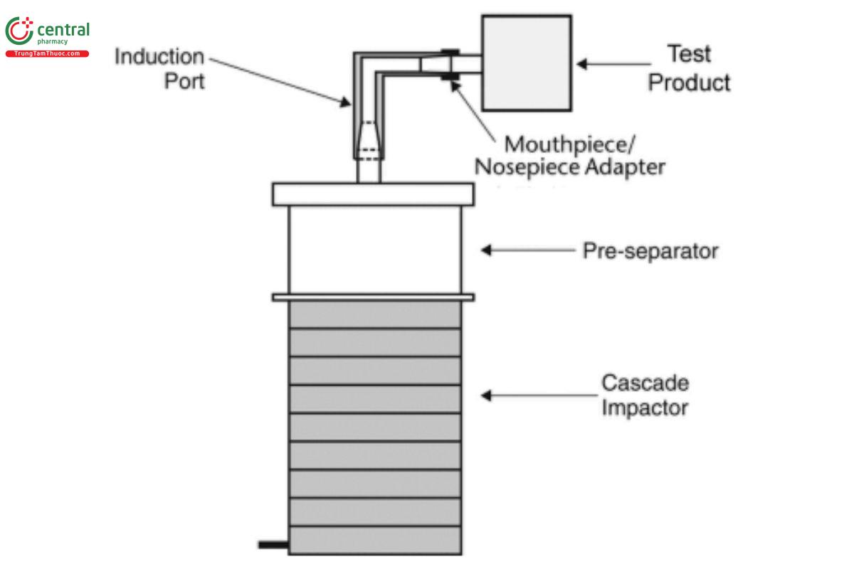
Figure 7a. Andersen Cascade Impactor with pre-separator: Assembly of induction port mounted onto cascade impactor with pre-separator.
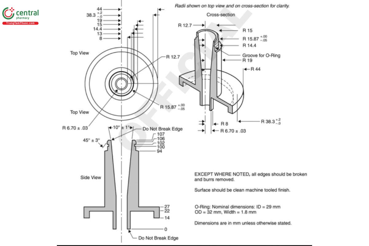
Figure 7b. Expanded views of top for the Andersen Cascade Impactor pre-separator for use at 28.3 L/min, adapted to the USP induction port. Material may be aluminum or stainless steel; interior bore should be polished to a surface roughness (Ra ) of approximately 0.40 µm.
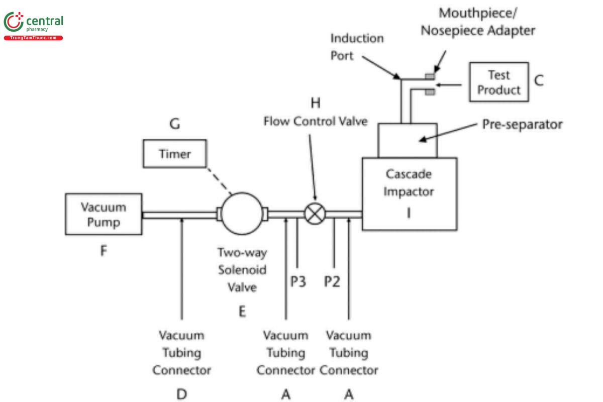
Figure 7c. Aerodynamic particle size distribution determination apparatus using Andersen Cascade Impactor or the Next Generation Impactor with pre-separator. The pre-separator is omitted for inhalation and nasal aerosol and inhalation spray drug products. (See Table 5 for component specifications.) [Note—The volumetric flow rate must be determined and fixed before the test product is inserted in Figure 7c.]
Table 5. Component specifications for Figure 7c
Code | Item | Description | |
A | Vacuum tubing connector | A short length of suitable vacuum tubing, e.g., silicone tubing with 10.0-mm ID, 16.0- mm OD, and a connector to pressure tap P2; internal volume 25 ± 5 mL | |
[Note—Impactor stage collection surfaces not shown.] | |||
C | Test product | Inhalation or nasal aerosol, spray, or powder products to be evaluated | |
D | Vacuum tubing connector | A short length of suitable vacuum tubing, e.g., silicone tubing with 16.0-mm ID and with or without a connector to pressure tap P3 | |
E | Two-way solenoid valve | 2-way, 2-port solenoid valve with an opening response time of ≤100 ms | |
F | Vacuum pump | Vacuum pump capable of drawing air through the complete assembly, including the filter, mouthpiece/nosepiece adaptor, and test product, at the required flow rate under critical (sonic) conditions (P3/P2 < 0.5) | |
G | Timer | Timer that switches current directly to the solenoid valve for the required duration. | |
H | Fllow-control valve | Adjustable regulating valve with flow coefficienta (Cv) ≥1 V | |
I | Cascade impactor | Andersen Cascade Impactor with or without preseparator or Next Generation Impactor with see Table 2 or without preseparator; | |
P2, P3 | Pressure tap | Pressure measurements determined under steady-state flow conditions with an absolute pressure transducer. The pressure taps must not be open to the atmosphere during sample collection. |
|
a Flow coefficient, as defined by ISA S75.02 Control valve capacity test procedures in Standards and Recommended Practices forInstrumentation and Control, 10th ed., Vol. 2. Research Triangle Park, NC: Instrument Society of America; 1989.
For operation at flow rates of 60 and 90 L/min, use manufacturers' alternate stage configurations. To ensure efficient particle capture, coat the particle collection surface of each stage appropriately with glycerol, silicone oil, or other suitable liquid unless this has been demonstrated to be unnecessary. Assemble the impactor as described in the manufacturer's literature with an after-filter below the final stage to capture any fine particles that otherwise would escape from the impactor. Place an appropriate predefined volume (up to 10 mL) of an appropriate solvent into the pre-separator, or coat the particle collection surfaces of the pre-separator to prevent re-entrainment of impacted particles. [Caution—Some solvents form flammable vapor–air mixtures that may be ignited during passage through a vacuum pump. Take appropriate precautions (alternative solvents, use of vapor traps, minimal pump operating times, etc.) to ensure operator safety during testing.] Attach a mouthpiece/nosepiece adapter to the end of the induction port to produce an airtight seal between the test product's mouthpiece/nosepiece and the induction port. Use a mouthpiece/nosepiece adapter that ensures that the tip of the test product's mouthpiece/nosepiece is flush with the open end of the induction port. Ensure that the various stages of the cascade impactor are connected with airtight seals to prevent leaks.
For flow rate calibration, turn on the vacuum pump, open the two-way solenoid valve, and determine the flow rate testing through the system as follows. Connect a flowmeter to the induction port. Use a flowmeter calibrated for the volumetric flow leaving the meter to directly determine Qout . Adjust the flow-control valve to achieve a steady flow through the system at the required rate, Qout , so that Qout is within ±5% of the value determined during testing for Delivered Dose Uniformity. Under steady-state flow conditions at the valve and at the flow rate to be used during testing ensure critical flow exists, by using the following procedure. With the product in place and the intended flow running, measure the absolute pressure on both sides of the flow-control valve (P2 and P3 in Figure 7c). A ratio of P3/P2 ≤0.5 indicates critical flow. If this ratio of P3/P2 is not achieved, switch to a more powerful pump, and remeasure the test flow rate. Adjust the timer controlling the operation of the two-way solenoid valve so that it opens this valve for a duration of 2T seconds based on determination of duration of T seconds for testing of Delivered Dose Uniformity.
C.3.2 Procedure—andersen cascade impactor with pre-separator
Perform the test using the Andersen Cascade Impactor with pre-separator at the flow rate, Qout determined earlier during testing for Delivered Dose Uniformity. Connect the apparatus to a flow-control system that is based on critical (sonic) flow as specified in Figure 7c (see also Table 5). Coat the particle collection surface of each of the stages of the cascade impactor appropriately to ensure that particles that have impacted on a given stage are not re-entrained in the owing airstream, as a consequence of particle bouncing, unless this has been shown to be unnecessary.
Prepare the inhalation powder or nasal powder according to the labeled instructions. With the vacuum pump running and the two-way solenoid valve closed, insert the test product's mouthpiece/nosepiece, held horizontally, into the mouthpiece/nosepiece adapter. Once the product is positioned, discharge the powder into the apparatus by opening the two-way solenoid valve for the required duration of 2T s, to sample 4.0 L of air, based on determined duration of T seconds for testing of Delivered Dose Uniformity. After the total volume of 4.0 L of air per actuation has been sampled, the two-way solenoid valve is closed and the test product is removed. If additional actuations are required for a determination, reload the test product powder according to the labeled instructions while inserted into the induction port mouthpiece/nosepiece adapter, and repeat the operation until the required number of actuations has been discharged. Certain types of inhalation or nasal powder products, e.g., capsule-based premetered or other powder product designs, may need removal of the test product from the mouthpiece/nosepiece adapter after each discharged dose for reloading of the device according to the labeled instructions. After each reload, reinsert the mouthpiece/nosepiece of the test product into the mouthpiece/nosepiece adapter. Repeat the same operation until the required minimum number of actuations has been discharged. After discharge of the last actuation, remove the test product from the mouthpiece/nosepiece adapter, and switch off the vacuum pump.
Carefully disassemble the apparatus. Using a suitable solvent, rinse the drug from the mouthpiece/nosepiece adapter, induction port, preseparator, each stage, and the collection plate of each stage and the filter immediately into appropriately sized flasks. [Note—Analyze all components separately. Only data from analysis of deposition on the collection plates should be used for the purpose of determination of stage deposition. The data from analysis of deposition on the other components should only be used for the purpose of establishing the determination of mass balance and should not be combined with the plate deposition for determination of aerodynamic particle size distribution.] Quantitatively dilute each flask to an appropriate volume. Using an appropriately validated method of analysis, determine the mass of drug collected in each of the samples.
4.4 Next Generation Impactor without Pre-separator for Inhalation Aerosols, Inhalation Sprays, and Nasal Aerosols
C.4.1 design—next generation impactor without pre-separator
The design and assembly of the Next Generation Impactor without pre-separator are shown in Figure 8a and Figure 8b. The induction port used to connect the impactor to a test product has the same internal dimensions as shown in Figure 6b. The device is a cascade impactor with seven stages and a micro-orifice collector (MOC). Use this apparatus at a flow rate of 30 L/min (±5%) unless otherwise prescribed in the individual monograph.
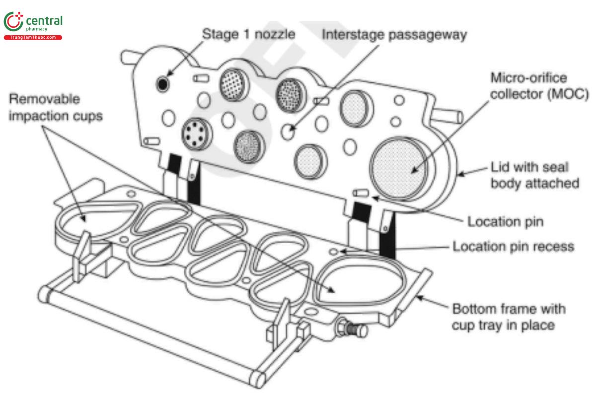
Figure 8a. Components and Nozzle configuration of the Next Generation Impactor.
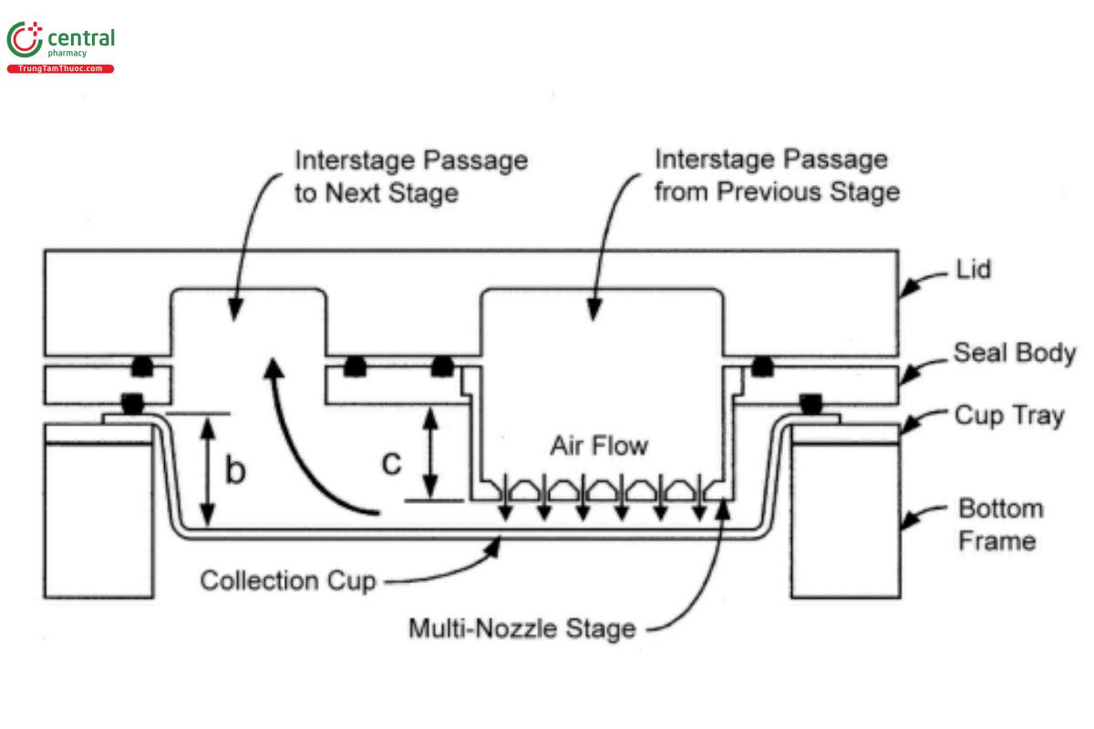
Figure 8b. A layout of interstage passageways of the Next Generation Impactor.
[Note—The Next Generation Impactor with pre-separator in place is presented in Figure 9a.]
The impactor layout has removable impaction cups with all of the cups in one plane. There are three main sections to the impactor: the bottom frame that holds the impaction cups, the seal body that holds the nozzles, and the lid that contains the interstage passageways.
Multiple nozzles are used at all but the first stage. The flow passes through the impactor in a saw-tooth pattern.
Stage mensuration is performed periodically (see C.1.1 Stage Mensuration) together with confirmation of other dimensions critical to the effective operation of the impactor. Critical dimensions are provided in Table 6.
Table 6. Critical Dimensions for the Next Generation Impactor
Description | Nominal Nozzle Diameter (mm) | Nominal Nozzle to Seal Body Distance (mm)a,b |
Pre-separatorc | 12.80 ± 0.05 | — |
Stage 1d | 14.30 ± 0.05 | 1.18 |
Stage 2d | 4.88 ± 0.04 | 5.236 ± 0.736 |
Stage 3d | 2.185 ± 0.020 | 8.445 ± 0.410 |
Stage 4d | 1.207 ± 0.010 | 11.379 ± 0.237 |
Stage 5d | 0.608 ± 0.010 | 13.176 ± 0.341 |
Stage 6d | 0.323 ± 0.010 | 13.999 ± 0.071 |
Stage 7d | 0.206 ± 0.010 | 14.000 ± 0.071 |
MOCd | ∼0.070 | 14.429–14.571 |
Optional cup depth (see b in Figure 8b) | 14.625 ± 0.100 | — |
Collection cup surface roughness | 0.5–2 µm | — |
a See Figure 8a.
b Refer to manufacturer for specifications on tolerance/precision of the dimensions.
c See Figure 9b.
d See Figure 8a.
During routine operation, the seal body and lid are held together as a single assembly. The impaction cups are accessible when this assembly is opened at the end of a product test. The cups are held in a support tray so that all cups can be removed from the impactor simultaneously by lifting out the tray.
The USP induction port (Figure 6b) is connected to the impactor inlet. A suitable mouthpiece/nosepiece adapter is used to provide an airtight seal between the test product's mouthpiece/nosepiece and the induction port.
The apparatus contains a terminal MOC that for most formulations may eliminate the need for a final filter if this capability is demonstrated by method validation. The MOC is an impactor nozzle plate and collection cup. The nozzle plate contains, nominally, 4032 holes, each approximately 70 µm in diameter. Most particles not captured on Stage 7 of the impactor may be captured on the cup surface below the MOC. There is an optional filter holder that can replace the MOC for formulations with a significant fraction of particles not captured by the MOC. Alternatively, an after-filter (glass fiber is often suitable) can be placed in a filter holder external to the Next Generation Impactor with and without pre-separator, which is located downstream of the MOC.
C.4.2 procedure—next generation impactor without pre-separator
Assemble the apparatus without the pre-separator. Place cups into the apertures in the cup tray. To ensure efficient particle capture, coat the particle collection surface of each stage with glycerol, silicone oil, or other suitable liquid, unless this has been demonstrated to be unnecessary. Insert the cup tray into the bottom frame, and lower into place. Close the impactor lid with the seal body attached, and operate the handle to lock the impactor together so that the system is airtight. Connect the USP induction port (Figure 6b) to the impactor inlet. Attach a mouthpiece/nosepiece adapter to the end of the induction port to produce an airtight seal between the test product’s mouthpiece/nosepiece and the induction port as shown in Figure 6a. Use a mouthpiece/nosepiece adapter that ensures that the tip of the test product's mouthpiece/nosepiece is flush with the open end of the induction port. Turn on the vacuum pump to draw air through the impactor, and calibrate the flow rate through the system with an appropriate flowmeter attached to the open end of the induction port.
Adjust the flow-control valve (see H in Figure 7c) on the vacuum pump to achieve steady flow through the system at 30 L/min (±5%).
Prepare the test product for use according to the label instructions for shaking, priming, and ring. With the vacuum pump running, insert the mouthpiece/nosepiece into the mouthpiece/nosepiece adapter and immediately fire into the cascade impactor the first of the minimum recommended number of actuations. Keep the valve depressed, as applicable, for a duration sufficient to ensure that the actuation has been completely discharged. If additional actuations are required for the sample, wait for 5 s before ring the next actuation. Repeat until the required number of actuations has been discharged. The number of actuations discharged must be sufficient to ensure an accurate and precise determination of aerodynamic size distribution. After the last actuation has been discharged, remove the test product from the mouthpiece/nosepiece adapter. Rinse the mouthpiece/nosepiece adapter and induction port with a suitable solvent, and dilute quantitatively to an appropriate volume.
Dismantle the apparatus, and recover the drug for analysis as follows. Remove the induction port and mouthpiece/nosepiece adapter from the apparatus, and extract the drug from each component of the system into an aliquot of solvent and recover quantitatively the drug substance from all inner surfaces. Open the impactor by releasing the handle and lifting the lid; remove the cup tray with the collection cups; and extract the drug substance in each cup into an aliquot of solvent. Using a validated method of analysis, determine the mass of drug contained in each of the aliquots of solvent. Only data from analysis of deposition on the collection cups should be used for the determination of stage deposition.
4.5 Next Generation Impactor with Pre-separator for Inhalation Powders and Nasal Powders
C.5.1 design—next generation impactor with pre-separator
The Next Generation Impactor is identical to that described in C.4.1 Design—Next Generation Impactor without Pre-separator (Figure 8a and Figure 8b), except that the pre-separator (Figure 9b) is used. A pre-separator may not be required for certain engineered powders, notably those of low bulk density. Connect the cascade impactor into the control system specified in Figure 7c.
C.5.2 procedure—next generation impactor with pre-separator
Assemble the apparatus with the pre-separator (Figure 9a).
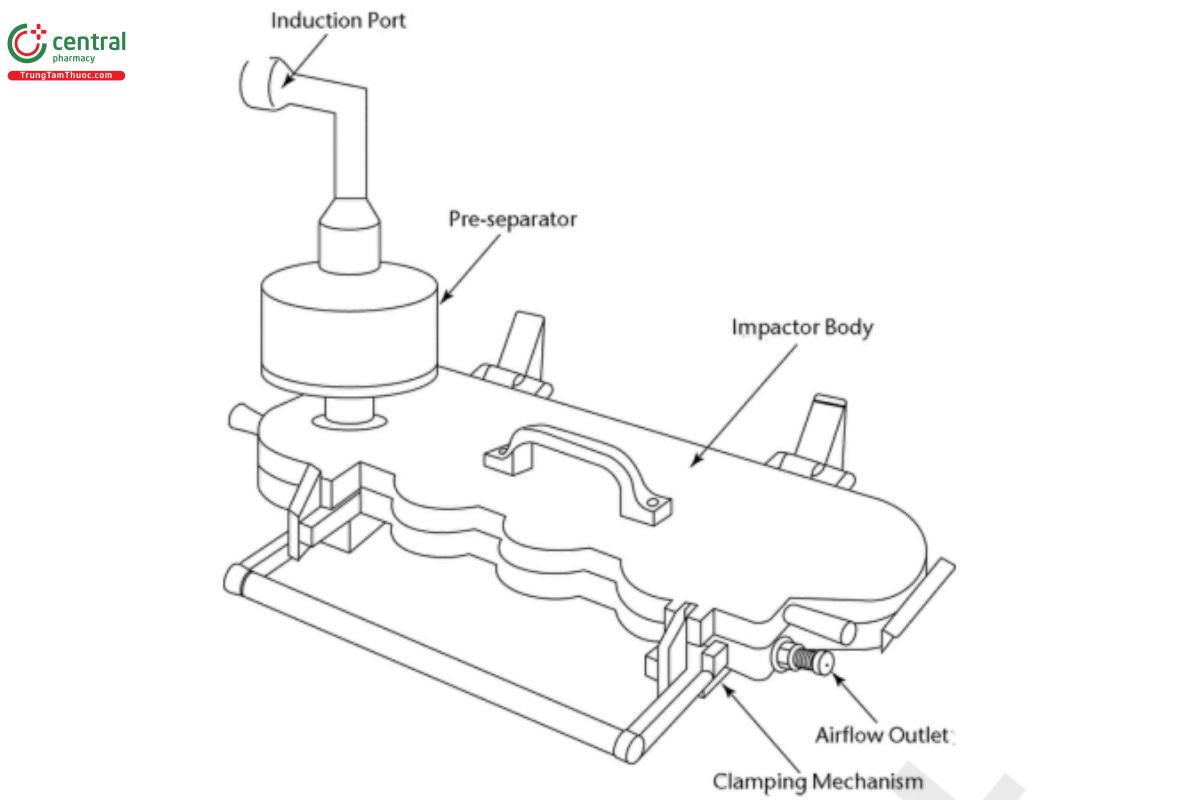
Figure 9a. Next Generation Impactor with pre-separator (shown with the pre-separator in place).
Place cups into the apertures in the cup tray (Figure 8a). To ensure efficient particle capture, coat the particle collection surface of each stage with glycerol, silicone oil, or other suitable liquid, unless it has been demonstrated to be unnecessary. Insert the cup tray into the bottom frame, and lower into place. Close the impactor lid with the seal body attached, and operate the handle to lock the impactor together so that the system is airtight.
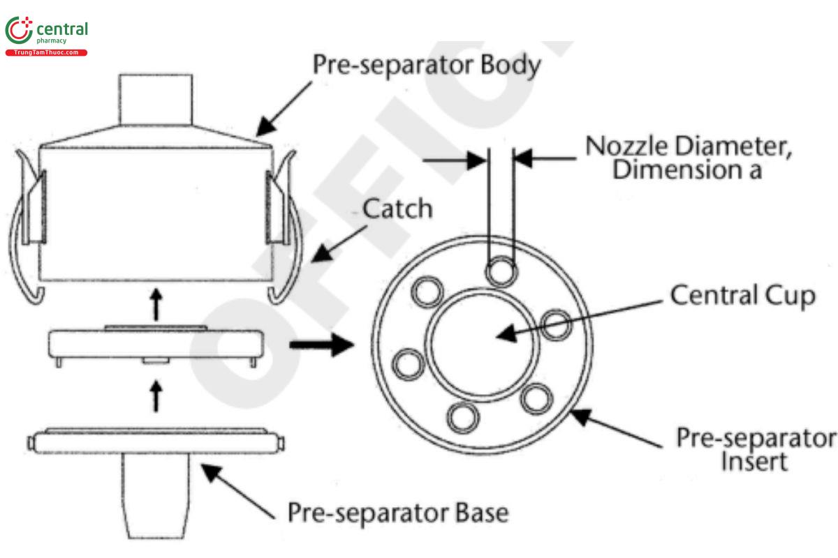
Figure 9b. Pre-separator layout for the Next Generation Impactor.
The pre-separator can be assembled as follows. Assemble the pre-separator insert into the pre-separator base; t the pre-separator base to the impactor inlet; add an appropriate predefined volume (up to 15 mL) of appropriate solvent used for sample recovery to the central cup of the pre-separator insert; place the pre-separator body on top of this assembly; and close the two catches. [Caution—Some solvents form flammable vapor–air mixtures that can be ignited during passage through a vacuum pump. Take appropriate precautions (e.g., alternative solvents, use of vapor traps, minimal pump operating times, etc.) to ensure operator safety during testing.]
Connect the USP induction port (Figure 6b) to the pre-separator inlet atop the cascade impactor (Figure 9a). Place a suitable mouthpiece/nosepiece adapter to the inlet of the induction port so that the mouthpiece/nosepiece end of the test product, when inserted, lines up along the horizontal axis of the induction port. The front face of the test product's mouthpiece/nosepiece is flush with the front face of the induction port, producing an airtight seal. When attached to the mouthpiece/nosepiece adapter, the test product should be positioned in the same orientation as intended for use. Connect the apparatus to a flow system according to the scheme specified in Figure 7c.
Conduct the test at the flow rate used in the test for Delivered Dose Uniformity, drawing 4.0 L of air from the mouthpiece/nosepiece of the product and through the apparatus. Connect a flowmeter to the induction port. Use a flowmeter calibrated for the volumetric flow leaving the meter. Adjust the flow-control valve (see H in Figure 7c) to achieve steady flow through the system at the required rate, Qout (±5%).
Ensure that critical flow occurs in the flow-control valve at the flow rate to be used during testing by using the following procedure. With the test product in place, and the intended flow running, measure the absolute pressure on both sides of the flow-control valve (P2 and P3 in Figure 7c). A ratio of P3/P2 ≤0.5 indicates critical flow. If this ratio of P3/P2 is not achieved, switch to a more powerful pump, and remeasure the test flow rate.
Prepare the inhalation powder or nasal powder according to the labeled instructions. With the vacuum pump running and the two-way solenoid valve closed, insert the test product's mouthpiece/nosepiece, held horizontally, into the mouthpiece/nosepiece adapter. Adjust the timer controlling the operation of the two-way solenoid valve so that it opens the valve for a duration of 2T s to sample 4.0 L of air, based on determined duration of T seconds for testing of Delivered Dose Uniformity. After total air volume of 4.0 L sampled per actuation, the two-way solenoid valve is closed and the test product is removed. If additional actuations are required for a determination, reload the inhalation powder or nasal powder according to the labeled instructions while inserted into the mouthpiece/nosepiece adapter, and repeat the operation until the required number of actuations has been discharged. Certain types of inhalation or nasal powder products, e.g., capsule-based premetered or other powder product designs, may need removal of the test product from the mouthpiece/nosepiece adapter after each discharged dose for reloading of the device according to the labeled instructions. After each reload, reinsert the mouthpiece of the test product into the mouthpiece/nosepiece adapter. Repeat the same operation until the required number of actuations has been discharged. After discharge of the last actuation, remove the test product from the mouthpiece/nosepiece adapter, and switch off the vacuum pump.
Dismantle the apparatus, and recover drug for analysis as follows. Remove the induction port and mouthpiece/nosepiece adapter from the pre-separator, and extract the drug from each component of the system into an aliquot of appropriate solvent; remove the pre-separator from the impactor without spilling the solvent into the impactor; and recover quantitatively the drug substance from all inner surfaces. Open the impactor by releasing the handle and lifting the lid. Remove the cup tray, with the collection cups, and recover the drug substance from each cup into an aliquot of solvent. Using a validated method of analysis, determine the mass of drug contained in each of the aliquots of solvent.
1International Pharmaceutical Aerosol Consortium on Regulation & Science (IPAC-RS), used with permission.
