Good Cascade Impactor Practices
If you find any inaccurate information, please let us know by providing your feedback here


Tóm tắt nội dung
- 1. INTRODUCTION
- 2. DEFINITIONS OF KEY TERMS RELATING TO THIS CHAPTER
- 3. CASCADE IMPACTOR OPERATING PRINCIPLES
- 4. APPARATUS MAINTENANCE
- 5. CASCADE IMPACTOR METHOD DEVELOPMENT
- 6. IN-USE ASPECTS
- 6.1 Initial Considerations
- 6.2 Inspection of Cascade Impactor Components Susceptible to Deterioration
- 6.3 Assurance of Stage Collection Surface Coating
- 6.4 Assertion of Correct Assembly
- 6.5 Mitigation of Air Leakage into the Apparatus
- 6.6 Setting of Flow Rate
- 6.7 Cleaning and Storage Between Uses
- 6.8 Assertion that Individual Cascade Impactor Assemblies of the Same Type (i.e., Andersen Cascade Impactor or Next Generation Impactor) are Interchangeable
This article is compiled based on the United States Pharmacopeia (USP) – 2025 Edition
Issued and maintained by the United States Pharmacopeial Convention (USP)
1 1. INTRODUCTION
1.1 1.1 Background and Rationale
The multi-stage cascade impactor is the mainstay methodology for the determination of aerodynamic particle size distribution (APSD) of aerosols emitted by Inhalation Aerosols and Sprays, and Inhalation Powders, as described in Inhalation and Nasal Drug Products: Aerosols, Sprays, and Powders—Performance Quality Tests 〈601〉. This equipment is also recommended for APSD assessment associated with the use of drug products dispersed by nebulizing systems in Products for Nebulization—Characterization Tests 〈1601〉 as well as for the assessment of add-on devices for use with inhalation aerosols in Spacers and Valved Holding Chambers Used With Inhalation Aerosols—Characterization Tests 〈1602〉. Both chapters provide instructions on how to determine APSD, but due to necessity are focused on the measurement process itself, and are therefore limited in the advice given to assist in obtaining consistent measurements by these apparatuses. The cascade impactor is a complex apparatus to set-up, use, and maintain correctly. This chapter provides guidance to optimize the accuracy and precision of the methods described in 〈 601〉, 〈1601〉, and 〈1602〉 for the determination of APSD.
Regulatory activity in the mid-1990s that led to the 1998 publication of a draft US FDA Guidance for Industry on metered dose inhaler (MDI) and dry powder inhaler (DPI) drug products chemistry, manufacturing, and controls documentation obviated the need for an informational chapter covering good cascade impactor practice (GCIP). This draft Guidance (Metered Dose Inhaler (MDI) and Dry Powder Inhaler (DPI) Products—Quality Considerations) was updated in 2018. Following the release of this document, the International Pharmaceutical Aerosol Consortium on Regulation and Science (IPAC-RS) and later the Product Quality Research Institute (PQRI), recognized that there was a need to define a method of addressing a failure to achieve a mass balance in the quality testing of orally inhaled products (OIPs). After the PQRI working group was concluded, the Cascade Impactor Working Group of the IPAC-RS continued to address reports from stakeholders that the cascade impactor method was complex, resulting in measurement failures that were not attributable to product quality. Later, the European Pharmaceutical Aerosol Group (EPAG) established the acceptability of stage mensuration as a means for a regular check on aerodynamic size-separating performance of the component stages and exploring methods of collection surface coating, eliminating leakage into the apparatus and setting the volumetric flow rate correctly.
The purpose of GCIP is therefore:
1. To ensure appropriate size-fractionation of the inhaled product;
2. To establish the APSD profile of the delivered dose reliably, minimizing sources of potential bias and optimizing measurement precision;
3. To obtain adequate resolution of the fine particle mass component of the delivered dose;
4. To establish the precision of manufacture of impactor apparatuses and accessories with consideration for allowed tolerances and material of construction; including information on calibration, verification, and mensuration-related issues of the apparatus upon receipt and after use.
The rationale for the chapter is to guide both new and existing cascade impactor equipment users as to industry best practices in connection with set-up, use, maintenance, and storage between uses. The ultimate goal is to establish and maintain the capability to determine the APSD and quality consistency of drug product batches.
1.2 1.2 Purpose and Scope
The purpose of this chapter is to define a series of measures that should be taken to improve the likelihood of reliably making valid measurements of APSD from a product for inhalation by any of the cascade impactor apparatuses described in 〈601〉. Its focus is on the measurement apparatus itself.
The scope is in four main parts:
1. Generic description of the operating principle of the cascade impactor;
2. Apparatus maintenance, including ancillary equipment such as the pre-separator (PS), used for some APSD measurements and the induction port entry to the measurement system;
3. Method development for inhaler APSD determinations, providing guidance on how to structure a series of measurements to obtain information regarding the variability associated with the determination, as well as advice regarding the mitigation of common causes of measurement bias;
4. In-use aspects, in particular the step-by-step checks that should be made before each measurement, addressing cleaning and storage of the apparatus components, maintaining the integrity of individual apparatus sets where more-than-one cascade impactor and the associated equipment is in service, and lastly advising on checks that should be made to provide assurance of component interchangeability following appropriate component validation procedure(s) (for example, the use of a common PS with several different impactors or the use of the same collection plate or cup in several different impactors of the same type).
This chapter is not intended to provide a line-by-line guide to APSD measurement, as some of this information is provided in 〈601〉, 〈 1601〉, and 〈1602〉 for the various inhaler product types. Neither does it provide detailed procedures, because in many cases, such information will be product-specific. Rather, the information presented is meant to summarize current thinking as to the implementation of best practices in cascade impactor maintenance and use in terms of robust protocols for the laboratory making these measurements. When developing such protocols, users are also advised to consult with current regulatory guidance documents that address inhaler APSD measurement, for example, those published from time to time by the FDA.
1.3 1.3 Specific Information Regarding Impactor Stage Mensuration
In 4.1 Stage Mensuration, Measurement Traceability, and Mensuration Interval, information regarding the stage optical mensuration of nozzles associated with the sizing stages of cascade impactors is given to aid the user in identifying the critical aspects of the process and how mensuration provides traceability of the measures of size ultimately to the international length standard via intermediate calibrated objects, such as optical reticles or orifices of known diameter, having a circular profile. However, since specialized optical inspection equipment is required to acquire the mensuration data, it is assumed likely that the user will employ a specialized service in order to undertake the task, so detailed methodology is not provided.
2 2. DEFINITIONS OF KEY TERMS RELATING TO THIS CHAPTER
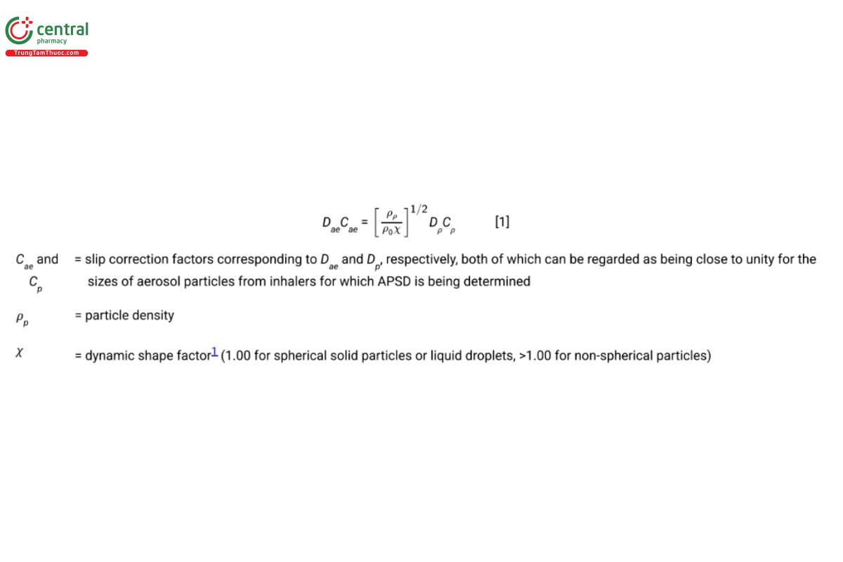
Aerodynamic diameter (Dae): The aerodynamic diameter of an irregular particle is defined as the diameter of the spherical particle with a density of water [1000 kg/m3 (ρ0)] and having the same settling velocity under the influence of gravity as the irregular particle. Dae is related to the microscopy-measured physical diameter (volume equivalent diameter, Dp) in accordance with:
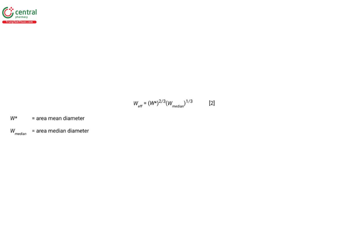
Effective diameter (Weff): The representative diameter for a collection of nozzles forming a multi-nozzle stage of a multi-stage cascade impactor. Effective diameter is defined analytically as the product of the area mean diameter (W*) raised to the power of 2/3 and the area median diameter (Wmedian) raised to the power of 1/3:
For a single-nozzle stage, Weff defaults to the mensurated diameter of that nozzle.
Stage cut-point size (d50): The size on the aerodynamic diameter scale at which a given impactor stage collects incoming particles with 50% efficiency. The relationship between collection efficiency and D is described further in 3. Cascade Impactor Operating Principles.
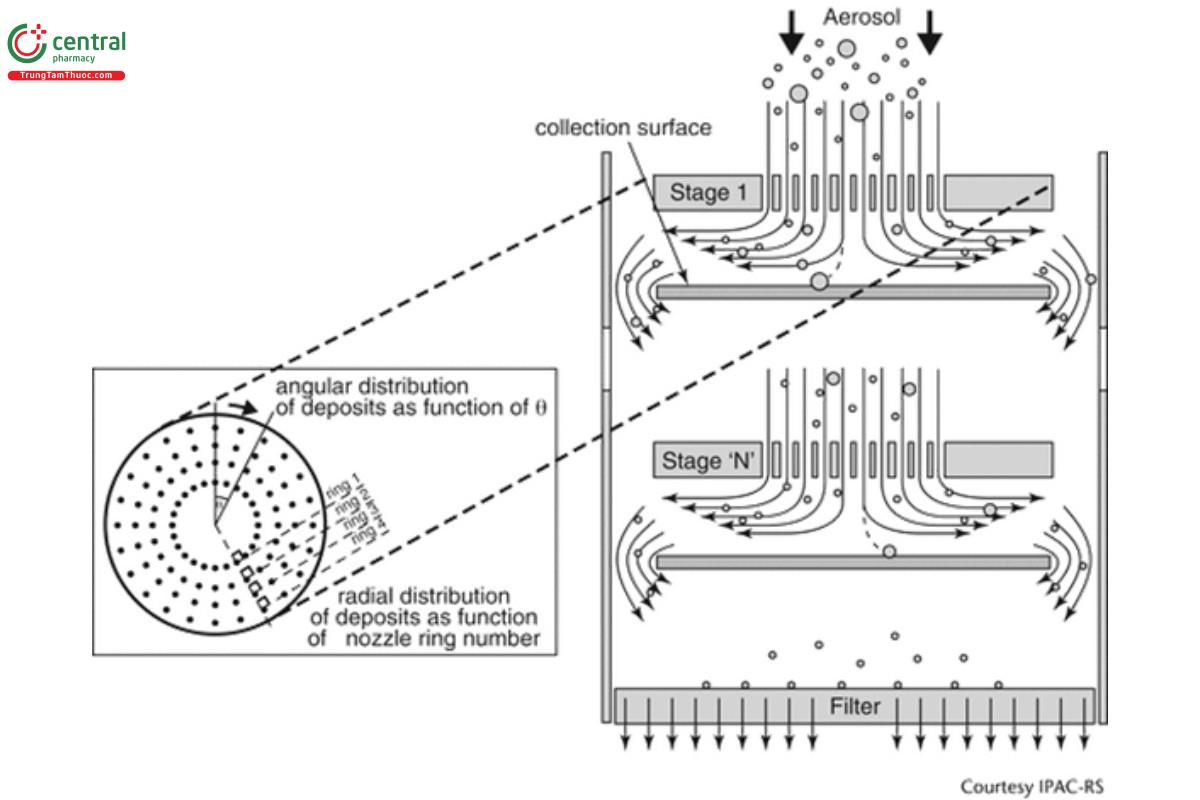
Stokes number (St): The dimensionless term characterizing the behavior of solid or liquid particles suspended in a fluid flow, such as air. A particle with a low Stokes number follows the air streamlines. In contrast, a particle possessing a large Stokes number is dominated by its inertia and so that it continues along its initial trajectory when the flow passes an obstruction, for example, as it diverges upstream of the collection surface of an impactor stage (see Figure 1). St is the Stokes number corresponding to the cut-point size at which the impactor stage is 50% efficient at collecting the incoming particles.
Stage mensuration: The process of establishing the representative diameter at the exit of each nozzle of a stage forming part of a multi- stage impactor. Although pin or go/no gauges can be used to mechanically measure nozzles having diameters in excess of about 2 mm, it is more common currently to make the determination non-invasively by using automated optical microscopy combined with image analysis.
3 3. CASCADE IMPACTOR OPERATING PRINCIPLES
A cascade impactor size-fractionates incoming aerosol particles into several sub-fractions on the basis of their differing inertia. A typical design, such as the apparatuses described in 〈601〉, comprises several consecutive stages, each of which functions as an inertial size- separator or fractionator of the incoming aerosol in a gas stream moving at constant velocity (flow rate). The basic component is a single stage that comprises a nozzle plate containing one or more circular orifices located a fixed distance from an impaction plate/cup surface that is usually horizontal (see Figure 1). The following characteristic dimensions describe the operating property of the stage:
Weff : effective nozzle diameter—most stages will contain n nozzles machined to be as close to identical as possible
T: thickness of the nozzle plate
S: separation distance between exit plane of nozzle plate and the collection surface
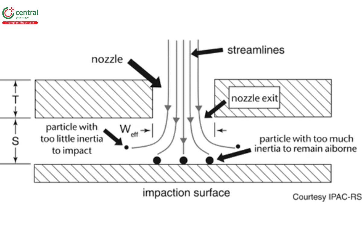
The stage functions by fractionating incoming particles of various sizes on the basis of their differing inertia, the magnitude of which reflects the resistance to a change in direction of the laminar flow streamlines passing through each nozzle. As the incoming flow passes through the nozzle plate, the streamlines diverge on approach to the collection surface, whereas the finite inertia of the particles causes them to cross the streamlines. Depending upon how far a given particle diverges from the streamlines, its trajectory may cause it to collide (impact) with the collection surface located at a distance, S, close to the exit plane of the nozzle set.
The magnitude of T is set by the manufacturer during design of the impactor stage, and in general, does not change measurably in use. In contrast, the size of S can be reduced by coating of the collection surface to mitigate particle bounce (see 5.4 Mitigation of Particle Bounce and Re-Entrainment), as well as by the accumulation of deposited particles on the collection surface. The ratio, S/Weff, can vary widely in the range 1–10 for effective size fractionation to occur, and therefore changes in this ratio are unlikely to influence stage performance, given typical mass loadings associated with inhaler APSD measurements, even on the stages where most of the particulate deposits.
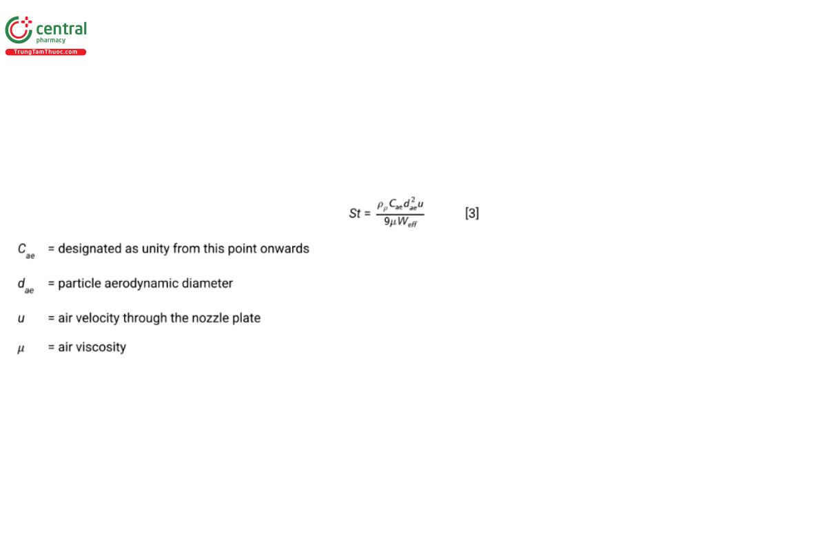
The dimensionless Stokes number (St), which is the ratio of the stopping distance of a particle to a characteristic dimension, in this case the nozzle diameter, Weff, describes the size fractionation process by defining a critical particle size that will reach the collection surface for a particular stage geometry. St is defined in terms of the stage effective diameter by the following relationship:
In a cascade impactor, several stages are connected together such that u progressively increases through the cascade by reducing Weff (see Figure 2).
Equation 4 predicts that the particle collection efficiency of an ideal impactor stage, Estage, expressed as a percentage, will increase in a step-wise manner between limits of 0%–100%, as dae increases. In practice, for a well-designed stage, Estage is a monotonic sigmoidal function of dae that increases steeply from E ≈ 0% to >95%, reaching its maximum steepness when Estage is 50% (see Figure 3). At this location, defined as the stage cut-off diameter (d50), this equation also defines the relationship between d50, St50, and volumetric flow rate (Q) for a multi-orifice stage comprising n circular nozzles:
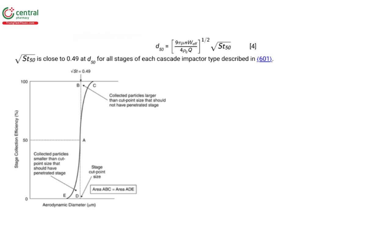
In a well-designed stage, the area ABC of Figure 3, representing the portion of the incoming aerosol contained in particles larger than the cut-point size that should have been collected, but instead bypassed the collection plate/cup, equals the corresponding area ADE that represents the portion of the aerosol contained in particles smaller than the cut-point size that should have penetrated the stage, but instead were collected there. The result is that d50 for a given stage can be used to define its size-fractionating performance as if it was ideal in this respect.
An important outcome arising from Equation 4 is that the cut-off diameters of all the stages in a given cascade impactor are constant only when Q is also constant. It follows that for the testing of dry powder inhalers in accordance with the methodology in 〈 601〉, the stage cut- points will not be at their final steady state values until the volumetric flow rate is constant after initiation of sampling from no flow by opening the two-way solenoid valve located between the exit from the impactor and the vacuum source. This process can take up to 400 ms for impactors having large internal volume, in particular, the Next Generation Impactor (NGI) with its PS. In practice, this finite start-up time is ignored in such assessments on the basis that it represents a small fraction of the total time during which the 4.0-L volume is sampled for inhalation powders. More importantly, however, any leakage of ambient air into the impactor at locations other than via the induction port, will increase the local value of Q after the leakage point, and in consequence result in an uncontrolled decrease in d50 for stages downstream. Bias arising from leakage into the impactor is therefore discussed further in 6 .5 Mitigation of Air Leakage into the Apparatus.
4 4. APPARATUS MAINTENANCE
4.1 4.1 Stage Mensuration, Measurement Traceability, and Mensuration Interval
The performance of a specific stage of a cascade impactor depends primarily upon the physical integrity of the nozzles. It follows that the precision of manufacture of these critical components is a factor that may contribute to variability of APSD results when measurements of the same inhaled product are made with more than one impactor. Furthermore, use-related changes to the nozzle dimensions of a given impactor may result in the development of APSD measurement bias during time in service. Mensuration is therefore appropriate both for new impactors and at intervals during their lifetime in service.
Nozzles can become partially plugged by deposited particles or through corrosion of the metal from which the stage nozzle plate is manufactured. Alternatively, they can become widened with time, either through corrosive action or by mechanical damage, for instance during cleaning if a sharp object is used to penetrate the nozzles. In the past, stage performance was determined by calibrating the stage with uniform-sized (monodisperse) particles of known aerodynamic diameter. However, the process is time-consuming as many different sizes of calibration particles are required to define the collection efficiency curve to the required precision. Since the advent of automated microscopy-image analysis, the procedure of stage mensuration has replaced particle calibration. In stage mensuration, the diameter of each nozzle exit is directly measured to a high degree of accuracy and precision, and the effective diameter (Weff) is calculated to represent the entire group of nozzles where more than a single nozzle is present. In the latter case, the single nozzle diameter is identical with Weff. The calculated value of Weff is compared with the tolerance range established for that stage for either the Andersen Cascade Impactor or the NGI in 〈601〉 to establish if the stage is within specification. The mensuration equipment is in turn calibrated with reference objects that are traceable ultimately to the international length standard. It is anticipated that the cascade impactor user will have the procedure undertaken by an external provider, who will typically be the supplier of the impactor, so the focus here is on establishing a regimen for maintaining assurance that any given stage of any cascade impactor remains within the manufacturer’s specification as defined in 〈 601〉.
The scheme shown in Figure 4 illustrates the components of a mensuration protocol for initial receipt and subsequent assessment of any of the impactors described in 〈601〉. The following checks are recommended:
1. Installation qualification (IQ): At receipt of a new impactor, ensure, as part of IQ, that each stage is compliant with the manufacturer’s dimensional specifications. These initial measurements are intended to establish baseline data for each stage of each individual cascade impactor. Undertake mensuration for each and every nozzle of each stage and determine its Weff. Compare this measurement against the critical dimensions specified for that stage/cascade impactor in 〈 601〉. Reject any stage whose Weff is outside the specification. For the ACI, it may be appropriate to substitute the equivalent rejected stage(s) with alternative stages of the same number(s), whose Weff value(s) are within specification. However, in the case of the NGI, the entire unit will need to be returned to the supplier for remedial action to provide stage(s) whose Weff values are within specification. Once values of Weff for all stages are ascertained to be within specification, the entire cascade impactor can be accepted for use.
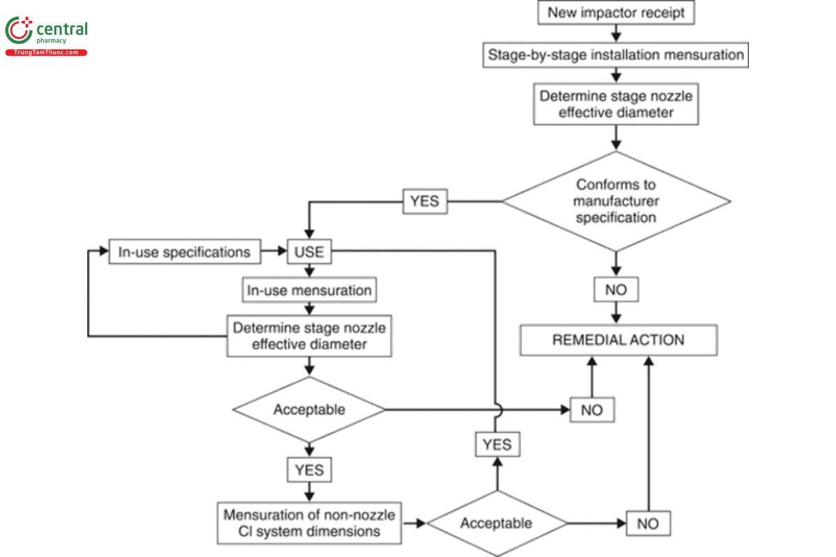
[NOTE—The frequency of the “In-use mensuration” check is determined by the amount of impactor use, the material from which the impactor is constructed, the product ingredients, and recovery solvent characteristics.]
2. For stages that are deemed acceptable in terms of the specifications in 〈601〉, establish the in-use stage mensuration regimen, whose
frequency is determined by the amount of impactor use and the product/active pharmaceutical ingredient solvent chemical characteristics. Each in-use mensuration will always include measuring the individual stage nozzle diameters, determining Weff as the performance metric. The specifications established at initial acceptance will normally be used as benchmarks to judge whether the stage(s) may continue in service or require remediation or replacement. Note that remediation could be as simple as careful cleaning to remove deposits that may be plugging nozzles. Acquisition of data from several subsequent mensuration exercises after exposure to the product(s) being evaluated in the typical testing environment may also provide the opportunity to develop meaningful in-service “at mensuration” limits for Weff for a given stage that will likely be chosen to be tighter than those used to begin with. These internal limits can subsequently be used to indicate the need for remediation before the stage Weff breaches either the upper or lower boundary of the tolerance range provided in 〈601〉.
3. Following mensuration failure of an impactor, undertake the following:
A. In the case of the ACI, remove those stages from service that are not acceptable in terms of the manufacturer’s specifications, and either recondition them or replace the affected stages altogether.
B. In the case of an NGI, the entire unit will need to be returned to the supplier for remedial action, if Weff for one or more stages is/are found to be out of specification.
4. Performance qualification (PQ): Establish the frequency between mensuration events. Although annual evaluation will be sufficient for most users, the duration between mensuration exercises should ideally be governed by the frequency of cascade impactor use, the type of compounds being collected, and the solvents used to recover the collected active pharmaceutical ingredient(s) particulate matter as well as the end user established cleaning procedures.
5. Ensure that other non-nozzle dimensional data for the cascade impactor apparatus are checked and confirmed as being acceptable through a mensuration or appropriate visual inspection process. Guidance on the important dimensions for ancillary equipment, such
as the induction port and PS (if used), has been provided by Nichols, et al.2 In the unlikely event that any of the critical dimensions (e.g., entry and exit diameters for the induction port, or nozzle diameters for the PS) are deemed to be unacceptable, remedial action may be as simple as cleaning the affected component. Under such circumstances, discussion with the manufacturer to establish the most appropriate procedure beforehand is strongly recommended. However, if remedial action does not resolve the problem, then the individual component should be replaced before the ancillary apparatus is placed back into service.
6. If any impactor stage or item of ancillary equipment fails specification, establish an appropriate remediation strategy, most likely involving the supplier/manufacturer of the affected equipment.
4.2 4.2 Internal Losses
Internal losses of particles on surfaces of the cascade impactor, other than the intended collection plates or cups, as well as losses associated with ancillary equipment, in particular the induction port and the PS (if used), are likely to result in a divergence in the recovered mass balance from the ideal label claim value. The magnitude of so-called wall losses, or inter-stage losses, if located within the impactor, is related to the issue of particle bounce covered in 5.4 Mitigation of Particle Bounce and Re-Entrainment, since particles having adhesive surfaces that have trajectories which graze internal surfaces of the apparatus are more susceptible to be retained there by virtue of their increased ability to adhere once initial contact is made. Furthermore, electrostatic charge associated with the aerosol/dry powder particles being sampled may also result in increased internal losses. Chapter 〈 601〉 therefore sets an upper limit of 5% of the total delivered drug mass per actuation from the inhaler as a validation requirement to limit the impact of such internal losses on measurement accuracy.
The magnitude of internal losses is also likely to be dependent on the physicochemical properties of the particles being sampled (e.g., surface roughness) that are in turn formulation dependent. Likewise, these losses are dependent upon the internal geometry of the passageways between stages of the impactor and are therefore different from one impactor design to another. In the initial development of a method for a new drug product or when a new design of cascade impactor is placed in service, it is recommended that internal surfaces of the induction port, PS (if used) and cascade impactor (entrance cone and nozzle plates for the ACI or inter-stage passageways for the NGI) be washed from both each other and from the collection surfaces separately with the established minimum necessary volume of recovery solvent to determine the magnitude of the associated internal losses as well as their location. In the product development stage, if the overall losses in APSD determination exceed 5% of the mass balance, and steps to mitigate particle bounce in the cascade impactor (see 5.4 Mitigation of Particle Bounce and Re-Entrainment) and electrostatic charge (see 5.5 Mitigation of Electrostatic Charge Accumulation) prove ineffective at reducing such losses, the user may wish to consider an alternative cascade impactor (e.g., replace the ACI with the NGI) to investigate if losses can be reduced below 5%. If this outcome is not possible, the inhaler aerosol APSD measurement procedure can be performed including the total internal wall losses in the assessment of mass balance to confirm that the mass recovery is within the recommended range of label claim for mass of active pharmaceutical ingredient delivered per actuation. In defining the ASPD profile, it is important to note that it is not possible to apportion wall losses from stage to stage within the cascade impactor in an attempt to assign specific size ranges to these losses. The wall loss deposition processes lack the requisite size selectivity associated with each impaction stage.
4.3 4.3 Inspection of Damaged/Deformed Collection Surfaces
Cascade impactors are typically manufactured from durable materials that are less prone than their predecessor materials (often aluminum) to chemical attack by solvents used in recovery of collected deposits. Nevertheless, the possibility remains that accidental damage may take place in use, especially to the more vulnerable components such as the collection plates (ACI) or collection cups/MOC (NGI). In the case of accidental damage, such as dropping during transit from one location to another, immediate physical inspection for superficial damage should be undertaken. The component should be taken out of use and replaced if damage/deformation is apparent, and is likely to affect performance.
5 5. CASCADE IMPACTOR METHOD DEVELOPMENT
5.1 5.1 Initial Considerations
The development of a cascade impactor-based method for evaluating the APSD of a specific inhaler product is typically undertaken in consultation with the appropriate regulatory authority. These authorities from time-to-time publish guidance to industry relating to the determination of APSD for inhaled products. The information provided in this part of this chapter is therefore intended to provide underlying information associated with good practice that is intended to assist in the process of establishing an acceptable methodology.
5.2 5.2 Number of Inhaler Actuations per Determination
Ideally, only one actuation from the inhaler product would be necessary for the APSD determination, and this situation may be possible for products having a high drug mass unit-dose delivery. In practice, more than one actuation may be needed to achieve the required deposition profile throughout the stages of the cascade impactor to enable acceptable measurement precision to be achieved by the drug recovery and assay procedure. However, repeated actuations may disguise any underlying variability in APSD that occur from one actuation of the inhaler to the next, and therefore it is recommended that determination for each inhaler should be performed with the minimum number of actuations justified by the sensitivity of the analytical procedure used to quantitate the deposited drug. The amount of drug deposited on the critical stages of the cascade impactor should be sufficient for reliable assay, but not so excessive as to bias the results by masking individual actuation variability. Here, critical stages are those that collect the smallest particle mass per actuation, where the sensitivity of the recovery method and subsequent assay for the active pharmaceutical ingredient are often limiting factors.
5.3 5.3 Number of Replicate APSD Determinations
Although the cascade impactor-based method for determining inhaler APSD performance is both a labor-intensive and exacting procedure, automated or semi-automated systems are available to assist in the process. It is common to undertake at least five replicate measurements at each condition being assessed. However, this number will typically be decided by consultation with the appropriate regulatory agency, involving considerations such as prior knowledge of the variability in delivery associated with the product and the number of actuations required through the delivery life of the inhaler.
5.4 5.4 Mitigation of Particle Bounce and Re-Entrainment
In normal operation, particles collected by a particular stage of the cascade impactor should be retained on the collection surface until the drug is recovered for assay. For certain inhalation aerosols containing surfactant as an excipient as well as products for nebulization that are generated as aqueous droplets, it is likely that the collection surfaces will not need coating with a viscous substrate to mitigate bounce of incoming particles and their subsequent re-entrainment in the flow passing further into the impactor. However, for inhalation powders, coating of collection surfaces other than the filter/MOC will almost certainly be necessary. Such pre-coating is normally used for inhalation powders where the incoming drug particles are accompanied by larger carrier particles.
Particle bounce and associated re-entrainment is easily diagnosed by the presence of a larger than expected mass of drug recovered from the back-up filter/MOC, because once re-entrained, the particles have sufficient velocity to bounce off the collection surfaces of subsequent stages. In method development, it is therefore recommended that evaluation of such behavior be undertaken in a validation study with and without collection surface coating present.
There are numerous methods for collection surface coating, all of which involve the deposition of a thin layer of a viscous substance, such as Glycerol, silicone oil, or other suitable substance, such as the surfactant, polyoxyethylene lauryl ether.3 The coating substance is typically prepared as a solution in a volatile solvent which subsequently evaporates, leaving behind a uniform deposit. The choice of coating material will depend upon the physicochemical properties of the drug product being sampled as well as the subsequent recovery and analytical procedure. Whatever method is chosen for applying the coating substance, each collection surface should be visually inspected for non- uniformities in the coating, and the procedure repeated after cleaning the collection surface, if imperfections are found.
The interior surfaces of the induction port are not normally coated in the procedures described in 〈601〉. However, an appropriate pre-defined volume of an appropriate solvent may be dispensed when the PS is used (up to 10 mL to coat the PS interior used with the ACI or up to 15 mL to the central cup of the PS used with the NGI). Alternatively, it may be appropriate to coat the particle collection surfaces with a viscous substance as described for the stage collection surfaces in order to prevent re-entrainment of impacted particles therein.
5.5 5.5 Mitigation of Electrostatic Charge Accumulation
Acquisition of electrostatic charge can affect the measured APSD by modifying the particle size properties of the aerosol delivered from the device (intrinsic aerosol electrostatic charge) or by changing the deposition of the aerosolized particles within the cascade impactor test assembly (delivery device/apparatus-acquired charging). Both processes result in an increase of variability of APSD measurements, especially when seasonal changes in relative humidity are not controlled, and such behavior is more likely with inhalation powders rather than inhalation aerosols or products for nebulization.
Appropriate setup and handling of the inhaler as well as the entire measurement apparatus can significantly reduce variability in test results caused by electrostatics, and practical steps include grounding the measurement equipment as well as the operator (typically via use of a wrist strap and an antistatic laboratory coat). Controlling the local environmental conditions such that testing is undertaken at values of relative humidity in the range 40%–60% is also recommended to avoid variability from electrostatic effects.
Change to read:
6 6. IN-USE ASPECTS
6.1 6.1 Initial Considerations
There are several precautions that should be taken for each and every cascade impactor measurement. The purpose of this section is to provide an ordered sequence of verifications [Operational Qualification (OQ)] for the user to follow to avoid bias associated with errors associated with apparatus set-up (i.e., incorrect impactor assembly) and also in the establishment of the correct operating conditions (i.e., flow rate setting). From a regulatory science perspective, the mass of active pharmaceutical ingredient deposited on a stage-by-stage basis is initially reported to establish the APSD profile of the drug product. At the appropriate time, stage groupings may be proposed based on agreement with the regulatory agency.
6.2 6.2 Inspection of Cascade Impactor Components Susceptible to Deterioration
Regardless of incidents involving accidental damage, a regimen should be established for periodic visual inspection of all cascade impactor apparatus components, including the induction port and PS (if used), connection tubing, and related flow control equipment. This physical examination is in addition to the stage mensuration of the nozzles of individual stages described in 4.1 Stage Mensuration, Measurement Traceability, and Mensuration Interval. The frequency of such inspections will depend upon the amount of use the components receive, as well as experience gained with time in service; however, as a start an annual inspection is recommended. Inspected components that are deemed damaged or marginally functional should be identified as such and removed from service. Visual inspection of the seal body and inter-stage passageways of the NGI can be difficult, and may therefore best be undertaken by the supplier/manufacturer. The component should be replaced or repaired to the manufacturer’s specification, if any damage/deformation is apparent.
The external ‘O’-ring seal associated with each stage of the ACI is particularly susceptible to crack formation in normal use. Each seal should therefore be visually inspected for cracking, scratch marks, and gross deformation on each occasion of use and replaced if damaged. The corresponding elastomer rings located in the seal body of the NGI should likewise be visually inspected before use and replaced if damaged.
6.3 6.3 Assurance of Stage Collection Surface Coating
Coating of the stage collection plates (ACI) or cups (NGI) may be necessary to mitigate bias in the APSD measurement caused by particle bounce and re-entrainment (see 5.4 Mitigation of Particle Bounce and Re-Entrainment). Since the coating procedure can be highly operator dependent, even if semi-automated, once a suitable coating method has been established and validated, each coated collection plate or cup should be visually inspected before assembly into the impactor to be sure that the applied coating is uniform and that no locations are apparent that remain uncoated.
6.4 6.4 Assertion of Correct Assembly
6.4.1 6.4.1 ANDERSEN CASCADE IMPACTOR
The individual stages are separated when the impactor is disassembled fully between determinations. The manufacturer may identify each nozzle plate with its stage number. However, if there is more than a single impactor in service, nozzle plates should be further identified as belonging to a particular impactor assembly, either by embossing the impactor serial number on the underside of each plate (so as not to affect the particle deposition surface), or by an acceptable means of identification, in order to preserve the integrity of the stage mensuration process by linking it to a specific cascade impactor assembly (see 4.1 Stage Mensuration, Measurement Traceability, and Mensuration Interval).
If an inhalation aerosol or spray is being tested, the stage order is as illustrated for configuration A in Table 1, and the cascade impactor is operated at 28.3 L/min for evaluating an inhalation aerosol or spray (see also 〈601〉 , Table 4 for critical nozzle dimensions). If an inhalation powder is under evaluation, there are three configurations A, B, and C of Table 1 for stage ordering, depending upon the target flow rate of 28.3 L/min, 60 L/min, or 90 L/min, respectively (see also 〈 601〉 , Table 3a for stage cut-point sizes).
The annular collection plates for the uppermost two stages are interchangeable, as are the solid surfaced plates for the following 6 stages so there is no need to identify each collection plate to belong to a specific impactor. However, during assembly it is important not to mix the order in which the two types of collection plate are assigned to each stage.
Following completion of the collection plate coating procedure (see 5.4 Mitigation of Particle Bounce and Re-Entrainment), set out the individual stages, each with their collection plate in the order in which they will be assembled (see Table 1) on the bench-top. Starting with the base-plate, insert a suitable filter disk into the recess of the filter stage and secure with the ‘O’-ring provided. Secure the filter stage on top of the base-plate. Locate the collection plate for the bottom-most size-fractionating stage on the three supports at the periphery of the filter stage, then secure the bottom-most stage nozzle plate to the filter stage. Continue assembling the stack vertically, first positioning the collection plate for the next stage, followed by securing the corresponding nozzle plate. Attach the inlet cone to the uppermost nozzle plate if an inhalation aerosol or spray is being tested, or the PS, assembled in accordance with the instructions in 〈601〉, if the impactor is being used to assess an inhalation powder, unless justified by data that PS is not necessary. Finally, secure the induction port to the entry of the inlet cone (inhalation aerosol or spray assessment) or PS (inhalation powder assessment) to complete the assembly of the impactor stack.
Table 1. The Three Configurations of the Andersen Cascade Impactor—Configuration A is Used at 28.3 L/min for the Evaluation of Inhalation Aerosols and Sprays; Configurations A, B, or C are Used for Evaluation of Inhalation Powders Depending Upon the Target Flow
Rate (28.3, 60, or 90 L/min, Respectively)
[NOTE—Stage ‘0’ is modified to accept stage ‘−1’ for operation at 60 L/min or stages ‘−1’ and ‘−2’ together for operation at 90 L/min. In either case, the inlet cone is replaced by the modified stage ‘0’ and used above either stage ‘−1’ or stage ‘−2’ depending upon the chosen flow rate.]
6.4.2 6.4.2 NEXT GENERATION IMPACTOR
There is only a single configuration of the NGI that can be operated at 15 L/min for the assessment of products for nebulization (see〈 1601〉 , Table 2), at 30 L/min for inhalation aerosols and sprays or at flow rates between 30 and 100 L/min for the assessment of inhalation powders (see 〈601〉, Table 3b (CN 1-May-2021) for stage cut-point sizes).
There are two sizes of collection cups; the two larger cups are located beneath the collection plate for stage 1 and under the MOC (or internal filter, if used), the six smaller cups are located beneath stages 2–7. Cups of a given size are interchangeable. Although this impactor can be operated without the cup tray, it is normal practice to insert the cups into the tray before each determination, since their order with respect to the stage number is easily preserved after each measurement by removing the tray and cups as a single unit from the bottom frame for transfer to the station where drug recovery takes place. Alternatively, multiple cup-sets may be used with a single cup tray or each cup set can be assigned to a particular cup tray, depending on the number of APSD determinations that need to be made per day, as well as the operating regimen in force within the laboratory. For instance, assigning cup sets to a particular tray is useful if separate operators are responsible for the APSD determination and subsequent drug recovery/assay processes. Nevertheless, it is advisable to mark the base of each cup so they are identified as a single set.
In typical use, following completion of the collection cup coating procedure (see 5.4 Mitigation of Particle Bounce and Re-Entrainment) and inspection of the seals in the seal body, each cup is located in the appropriate order in the cup tray. The MOC is normally present to capture any particles that penetrate beyond stage 7. However, for some inhaled products (i.e., inhalation aerosols dispersing a plume in which a significant portion of the particles have sizes finer than about 1.0 μm in aerodynamic diameter), the MOC is replaced by either an internal filter and/or a separate external filter assembly which can be inserted between the impactor body and the vacuum source. Next, insert the cup tray into the impactor, such that the cup bases fit into the corresponding spaces of the bottom frame. Close and secure the seal body containing the stages nozzle plates over the cup tray using the external lever located at the front of the impactor. Insert the tapered fitting of the induction port to the entry port located on the uppermost surface of the seal body if an inhalation aerosol or spray is being tested.
Alternatively, insert the tapered fitting of the PS, assembled in accordance with the instructions in 〈 601〉, if the impactor is being used to assess an inhalation powder, unless justified by data that PS is not necessary, and secure the induction port to the entry of the PS to complete the assembly of the impactor.
6.5 6.5 Mitigation of Air Leakage into the Apparatus
Equation 4 in 3. Cascade Impactor Operating Principles illustrates the relationship between impactor stage cut-point sizes and volumetric flow rate of the air through the cascade impactor. Since the source of the air flow through the measurement apparatus is by the creation of a vacuum downstream of the impactor exit and the flow rate is set at the entry to the induction port (see 6 .6 Setting of Flow Rate), it follows that any leakage of ambient air into the sampling train at the time of setting the flow rate for the determination, other than via the intended entry of the induction port will result in an unintended increase in flow rate through stages downstream of the leak. In consequence, such leakage will result in bias of part or all of the APSD towards coarser sizes. Avoidance of air leakage is therefore a paramount requirement that should be verified before every APSD measurement.
Leakage testing is most conveniently undertaken immediately following assembly (see 6 .4 Assertion of Correct Assembly) by connecting the set-up, including the induction port, PS (if used), and external filter (if used with the NGI), to the vacuum source. This procedure also serves to check the leakage integrity of the entire set-up including tubing and flow control equipment before use. The entry of the induction port is temporarily plugged with an elastomeric bung for the duration of the test. Figure 5 illustrates the configuration for the ACI without PS, but the external components, if equipped with its PS or for the NGI with/without PS, are similar. A side-connection via a gate valve (G2) is made to a sensitive differential pressure transducer (0–50 kPa and capable of determining a change of ±0.5 kPa at 20.0 kPa) that is located immediately after the exit port from the cascade impactor or the external filter assembly if the NGI is used with this additional equipment. Another gate valve (G1) is located between the side-connection and the variable flow control valve that, in turn, is connected to the vacuum source/pump.
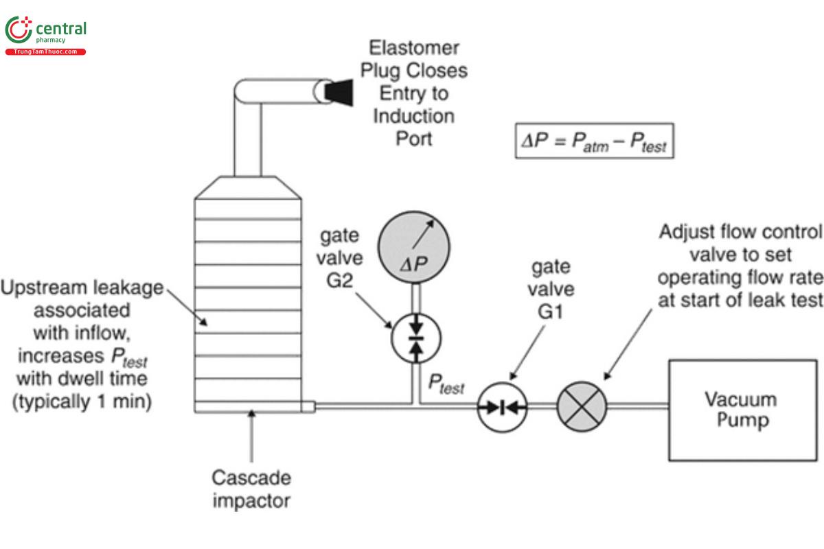
[NOTE—The system is shown for inhalation aerosols, but the same procedure will work by substituting the appropriate flow control equipment for testing inhalation powders in place of the flow control valve.]
The following procedure is then followed:
1. With the flow control valve closed, the gate valves, G1 and G2, are opened, and the vacuum source is activated;
2. A partial vacuum is applied to the test system by adjusting the flow control valve to set P0 to 20.0 ± 0.5 kPa observing the reading of the output from the differential pressure meter. The differential pressure is measured by connecting the differential pressure transducer at its negative pressure port to the side-connection from the test system;
3. After the required vacuum is displayed on the meter of the pressure gauge, the gate valve, G1, is fully closed to isolate the test apparatus from the vacuum source, and a timer is started;
4. The initial differential pressure (P0) is documented;
5. Allow at least 1 min to elapse, then observe and record the displayed pressure (P1);
6. Carefully remove the rubber bung from the inlet, ensuring not to disturb the apparatus, close the gate valve, G2, and open the gate valve, G1, to isolate the differential pressure meter and to bring the entire test system back to atmospheric pressure conditions, ready for next use;
7. The vacuum source can be deactivated at this stage;
8. The leak rate (L) is calculated in accordance with Equation 5:
L = (P0 − P1)/t [5]
P0 = initial differential pressure
P1 = displayed pressure
t = time (min)
Use the leak test specification from the manufacturer. If this is unavailable, then L should be ≤10 kPa/min.
If L exceeds this limit, examine the components of the assembly for leakage(s). Begin by inspecting the seals associated with the stages, then the connections from the induction port to PS (if used) or to cascade impactor, and finally from the impactor to the vacuum source.
Replace defective components as necessary and reassemble. Repeat the leak test above until L is lower than the specified limit.
6.6 6.6 Setting of Flow Rate
In 3. Cascade Impactor Operating Principles, Equation 4 links the stage cut-point sizes of the cascade impactor to the air volumetric flow rate through the apparatus. It follows that the accuracy of a measured APSD is critically dependent upon the flow rate setting. The flowmeters supplied by some impactor manufacturers that are located between the impactor exit and the vacuum source should be treated as flow indicators and NOT used as a means of setting flow rate.
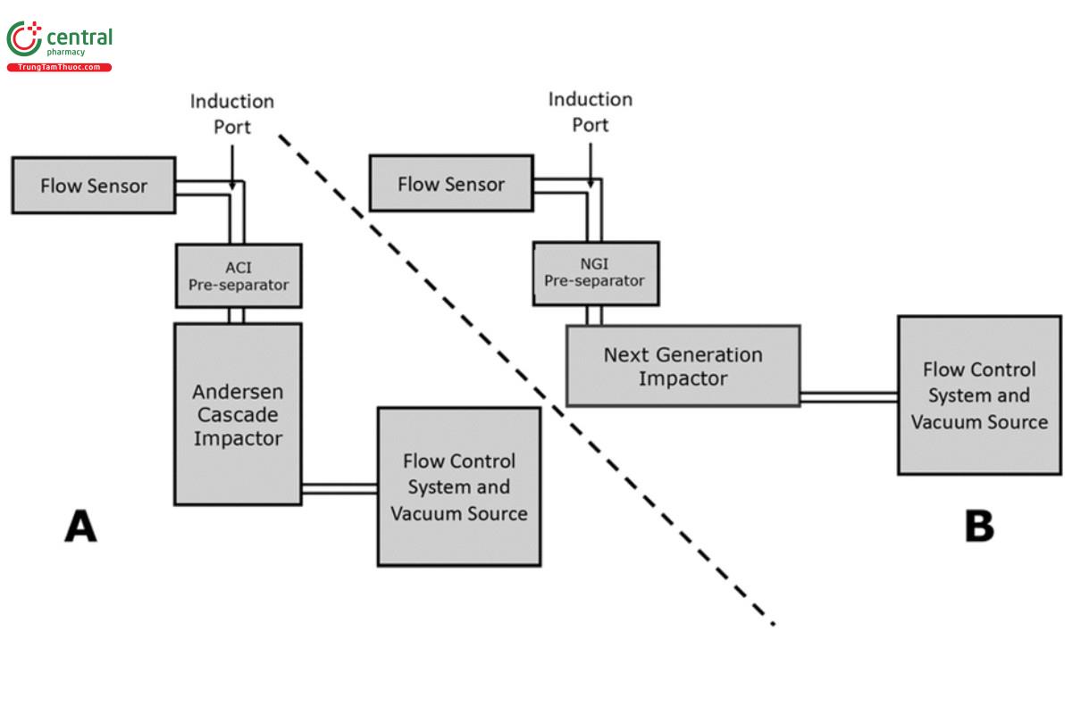
The volumetric flow rate is set at the entry of the induction port, as illustrated in Figure 6 .
Set the volumetric flow rate to the target value for the inhaler being tested immediately before making the APSD determination. Note that a low flow resistance mass flowmeter may be used to make this measurement, as the air pressure at the point of flow measurement is close to room ambient.
6.7 6.7 Cleaning and Storage Between Uses
Although cascade impactors and their related equipment are constructed from durable materials, careful storage between uses will prolong the life of vulnerable components, such as seal rings and collection plates/cups. A regimen should be established that ensures that all components are cleaned periodically, especially the nozzle plates (ACI) and the inter-stage passageways of the seal body (NGI). The frequency of cleaning will depend upon the chemical properties of the formulations being assessed as well as the drug recovery solvent(s).
If cascade impactor equipment is not in continuous use, it should be stored at room ambient temperature, in a dry environment, and protected from airborne contaminants. The collection plates/cups should be stored separately from the impactors and also protected from airborne contaminants.
6.8 6.8 Assertion that Individual Cascade Impactor Assemblies of the Same Type (i.e., Andersen Cascade Impactor or Next Generation Impactor) are Interchangeable
In many laboratories, there are likely to be many cascade impactor assembles of the same type in service. There may therefore be a desire to interchange different impactors when making APSD performance measurements on the same inhaler product in order to speed up the process. Provided that stage mensuration (see 4.1 Stage Mensuration, Measurement Traceability, and Mensuration Interval) has demonstrated that Weff, determined as the representative measure of the diameter of the nozzles of each stage is within the manufacturer’s specification, as provided in 〈601〉 , Table 4 (ACI) and 〈 601〉, Table 6 (CN 1-May-2021) (NGI), and checks have been made to ensure that seals are intact (see 6 .2 Inspection of Cascade Impactor Components Susceptible to Deterioration), and other considerations as discussed in 4. Apparatus Maintenance. The impactors may be interchangeable. However, it is advisable to perform comparative testing to validate equivalence.
Nevertheless, it is recommended that the stages together with their collection surfaces are uniquely identified to a particular cascade impactor assembly for the purpose of traceability as to the source for each APSD determination.
A similar consideration applies to the PS used with the NGI, because there is a specification for the nozzle diameters in 〈601〉, Table 6 . The situation is less clear for the PS for the ACI, although a manufacturer-supplied specification for the diameter of the three exit tubes, where available, would fulfill the same purpose as the PS specification for the NGI PS.
The specifications for the critical dimensions (entry and exit tube internal diameters) of the induction port are provided in 〈601〉, Figure 6b (CN 1-May-2021) and should be used to check for the interchangeability of this component, where multiple induction ports are in service.
1 Hinds W.C. 1999 “Properties, Behavior and Measurement of Airborne Particles.” Wiley Interscience, NY 1999.
2 Nichols SC, Mitchell JP, Shelton CM, Roberts DL. Good cascade impactor practice (GCIP) and considerations for “in-use” specifications. AAPS PharmSciTech. 2013;14(1):375–390.
3 Polyoxyethylene-23-lauryl ether.
